سلسلة تصميم الأعمدة W4: دراسة حالة هندسية نهائية
تربط دراسة الحالة هذه بين العناصر الرئيسية لتصميم الأعمدة التي تم تناولها في المقالات الستة السابقة، وهي: أساسيات صواني الصمامات، ومعايير التصميم، والحسابات الهيدروليكية، والصواني عالية الكفاءة، وتحسين التشغيل، وأدوات المحاكاة.
يتناول المشروع عمود التقطير الرئيسي للميثانول T-202 في مجمع كيميائي للفحم تبلغ طاقته الإنتاجية المعلنة 300,000 طن سنويًّا. ويشمل الاستعراض مسار العمل الكامل للتصميم، بدءًا من بيانات حزمة العمليات والحسابات اليدوية الأولية وصولاً إلى النمذجة الدقيقة باستخدام برنامج RadFrac، والتحقق الهيدروليكي باستخدام برنامج KG-TOWER، ورسومات البناء النهائية.
تحليل بيانات العمليات
يدير مجمع الكيماويات الفحمية وحدة لتخليق الميثانول تبلغ طاقتها المعلنة 300,000 طن سنويًّا، وتعمل 8,000 ساعة في السنة. ويدخل الميثانول الخام من قسم التخليق أولاً إلى العمود التمهيدي T-201، حيث تتم إزالة المكونات الخفيفة مثل إيثر ثنائي الميثيل والغازات المذابة.
ثم يتدفق التيار السفلي من T-201 إلى العمود الرئيسي T-202 لفصل الميثانول عن الماء.
شروط التصميم T-202
- معدل التغذية: 38.5 طن/ساعة
- تركيب المادة الخام: 82.0 بالوزن من الميثانول و18.0 بالوزن من الماء
- حالة المادة: سائلة عند درجة تكوّن الفقاعات
- إنتاج الخط العلوي: 36.5 طن/ساعة من الميثانول بنسبة نقاء 99.95٪ بالوزن (%)
- مياه الصرف من القاع: 2.0 طن/ساعة مع نسبة ميثانول أقل من 100 جزء في المليون
- ضغط التشغيل: 0.03 ميجا باسكال غاسي عند قمة العمود
- طريقة تحديد الخصائص: NRTL، مع استخدام بيانات التوازن بين البخار والسائل المستمدة من قاعدة بيانات Aspen Plus APV72
يتم حساب النسب المولية للمواد المُغذية باستخدام الأوزان الجزيئية التالية: 32.04 للميثانول و18.02 للماء.
تتضمن معدل التغذية البالغ 38.5 طن/ساعة ما يلي:
- الميثانول: 31.57 طن/ساعة، أي ما يعادل 985.9 كيلومول/ساعة
- الماء: 6.93 طن/ساعة، أي ما يعادل 384.6 كيلومول/ساعة
- إجمالي التدفق المولي: 1,370.5 كيمول/ساعة
وتتكون تركيبة العلف المقابلة مما يلي:
xF = 0.719 جزء مولي من الميثانول
التركيبات المذكورة للمنتجات هي:
- تكوين الصورة من أعلى: xD = 0.997
- تركيب السراويل: xB = 0.00006
الحسابات اليدوية الأولية
الحد الأدنى لعدد المراحل النظرية وفقًا لمعادلة فينسكي
يُفترض أن متوسط التقلب النسبي لنظام الميثانول والماء هو:
αavg ≈ 4.5
تمثل هذه القيمة متوسطًا مدمجًا مستمدًا من نموذج NRTL عبر نطاق التركيز الكامل. وتبلغ القابلية النسبية للتطاير حوالي 7.5 في منطقة التركيز المنخفض للميثانول وحوالي 3.5 في منطقة التركيز المرتفع للميثانول.
يُحسب الحد الأدنى لعدد المراحل النظرية على النحو التالي:
بإجراء التعويض بالقيم المذكورة:
يتم تقريب النتيجة الأولية إلى:
Nmin = 5 مراحل، بما في ذلك جهاز إعادة التسخين
نسبة الارتجاع الدنيا
في حالة التغذية بالسائل بنقطة الفقاعة:
يُقدَّر تكوين البخار في حالة التوازن المطابق لتكوين المادة المُغذية على النحو التالي:
نسبة الارتجاع الدنيا المحددة هي:
لذلك:
Rmin = 0.38
العدد الفعلي للمراحل النظرية باستخدام معامل الارتباط لجيلاند
نسبة الارتجاع التشغيلية المختارة هي:
وينتج عن ذلك:
على الرغم من أن نسبة الارتجاع هذه مرتفعة نسبيًا، إلا أنها تهدف إلى توفير ميثانول بنقاوة من الدرجة AA ومرونة تشغيلية كافية.
يتم حساب متغيرات جيلاند على النحو التالي:
ثم يُقدَّر العدد النظري للمراحل على النحو التالي:
تشمل هذه القيمة المكثف وجهاز إعادة التسخين.
ومع ذلك، فإن هذه النتيجة تستند إلى افتراض ثبات التقلب النسبي. ففي منطقة الميثانول عالي النقاء، ينخفض التقلب النسبي إلى ما دون 3.5. ولذلك، فإن استخدام قيمة ثابتة تبلغ 4.5 قد يؤدي إلى التقليل من تقدير العدد المطلوب من المراحل النظرية.
أشار نموذج التوازن بين البخار والسائل RadFrac الدقيق إلى الحاجة إلى:
24 مرحلة نظرية، بما في ذلك المكثف وجهاز إعادة التسخين
تبلغ هذه القيمة حوالي 3.4 أضعاف التقدير الأولي. وتُظهر النتيجة مبدأً تصميمياً مهماً:
تحدد الحسابات اليدوية الاتجاه الأولي، بينما توفر المحاكاة الدقيقة الدقة المطلوبة في التصميم.
القطر الأولي للعمود باستخدام طريقة ساودرز-براون
الشروط العامة المذكورة هي:
- درجة الحرارة: 65 درجة مئوية
- الضغط المطلق: 0.13 ميجا باسكال أ
- كثافة البخار: 1.48 كجم/م³
- كثافة السائل: 750 كجم/م³
يُقدَّر تدفق البخار العلوي على النحو التالي:
القيم المعلنة المقابلة هي:
- تدفق كتلة البخار: 88,440 كجم/ساعة
- التدفق الحجمي للبخار: 19.2 م³/ثانية
معامل تدفق البخار والسائل هو:
بالنسبة لمسافة تباعد الصواني البالغة 600 مم، تعطي معادلة «فير» النتيجة التالية:
سرعة التدفق هي:
باستخدام 80% من سرعة الفيضان:
مساحة المقطع العرضي المطلوبة هي:
القطر المقابل هو:
وبالتالي، يتم اختيار القطر الاسمي الأولي على النحو التالي:
DN4000

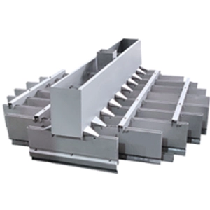
الشكل 1. ترتيب عمود T-202 المكون من 48 صينية صمامات من طراز F1، بقطر اسمي يبلغ DN4000، و24 صينية في كل من قسمي التصحيح والتجريد
نمذجة RadFrac الدقيقة
تحدد الحسابات اليدوية نطاق التصميم الأولي، بينما يحدد النموذج الدقيق متطلبات الفصل النهائية.
يحتوي العمود على 48 صينية فعلية. وبافتراض أن الكفاءة الإجمالية للصواني تبلغ 50%، فإن هذه الصواني تمثل 24 مرحلة نظرية. ويُعرَّف المكثف الكلي بأنه المرحلة 1، بينما يُعرَّف جهاز إعادة التسخين الخاص بالغلاية بأنه المرحلة 24.
يدخل التغذية عند المرحلة 12.
إعدادات نموذج RadFrac
- طريقة تحديد العقار: NRTL-RK
- نموذج الطور السائل: نموذج معامل النشاط وفقًا لـ NRTL
- نموذج الطور البخاري: معادلة الحالة لريدليش-كوونغ
- عدد المراحل: 24، بما في ذلك المكثف الكلي ومُعيد التسخين الخاص بالغلاية
- مرحلة التغذية: المرحلة 12
- حالة التغذية: سائل بنقطة الفقاعة يتم حسابه تلقائيًا بواسطة برنامج Aspen Flash
- المواصفات التشغيلية: نسبة الارتجاع 1.8 وتدفق المُقطَّر 985.9 كيلومول/ساعة
- طريقة التقارب: نيوتن-رافسون
- أداء التقارب: أربع دورات تكرارية مع بقايا أقل من 10⁻⁵
- مواصفات التصميم: تركيز الميثانول في الغاز العالي لا يقل عن 99.95 بالوزن، مع ضبط نسبة الارتجاع تلقائيًا
النتائج المجمعة
- إنتاج خط الإنتاج العلوي: 36.5 طن/ساعة من الميثانول بنسبة نقاء 99.952٪ بالوزن (%)
- مياه الصرف من القاع: 2.0 طن/ساعة تحتوي على 85 جزء في المليون من الميثانول
- قدرة المكثف: 12.8 ميجاوات
- ارتفاع درجة حرارة مياه التبريد: 15 درجة مئوية
- تدفق مياه التبريد المعلن: 61.3 طن/ساعة
- قدرة جهاز إعادة التسخين: 13.5 ميجاوات
- وسيط التسخين: بخار بضغط 0.3 ميجا باسكال ج
- استهلاك البخار المعلن: 21.8 طن/ساعة
- درجة الحرارة في الجزء العلوي من العمود: 64.8 درجة مئوية
- درجة الحرارة في مرحلة التغذية: 78.3 درجة مئوية
- درجة حرارة قاع العمود: 99.2 درجة مئوية
التحقق الهيدروليكي التفصيلي في برج KG-TOWER
يتم استيراد ملامح تدفق البخار والسائل التي تم الحصول عليها من برنامج RadFrac إلى برنامج KG-TOWER لإجراء التحقق الهيدروليكي لكل صينية على حدة.
معلمات الدرج المحددة هي:
- قطر العمود: DN4000
- المسافة بين الصواني: 600 ملم
- ارتفاع السد: 50 ملم
- طول السد: 2.4 م، أي ما يعادل 0.6D
- عدد الصمامات من طراز F1: 850
- نسبة المساحة المفتوحة: 12.8%
فحص الفيضانات
يُعتبر الدرج العلوي العامل الهيدروليكي المحدد.
تُعبَّر سرعة البخار السطحية الفعلية بالصيغة التالية:
وبالتالي، فإن نسبة الفيضان هي:
النتيجة: 83.2%، ضمن النطاق المفضل المحدد بين 60% و85%
معامل الطاقة الحركية لثقب الصمام
بالنسبة لصمام واحد يبلغ قطر فتحته 49 ملم، فإن المساحة الإجمالية للفتحة هي:
سرعة الثقب هي:
معامل الطاقة الحركية هو:
النتيجة: F₀ = 14.5، ضمن النطاق المفضل المحدد الذي يتراوح بين 8 و15
تشير هذه القيمة إلى مقاومة كافية للتسرب في ظل ظروف التصميم.
زمن البقاء في أنبوب الهبوط
مساحة أنبوب الهبوط المحددة على أحد الجانبين هي:
حجم الأنبوب الهابط هو:
معدل تدفق السائل هو:
مدة البقاء هي:
النتيجة: 18.6 ثانية، وهو ما يتجاوز الحد الأدنى المحدد البالغ خمس ثوانٍ
وبالتالي، فإن أنبوب الهبوط يوفر وقتًا كافيًا لفصل البخار في ظل شروط التصميم المذكورة.
التناغم
باستخدام معامل الارتباط «Glitsch» عند نسبة الفيضان البالغة 83.2%:
النتيجة: 0.038 كجم سائل/كجم بخار، أي أقل من الحد المحدد البالغ 0.1
مرونة التشغيل
عند الحمل 50%:
ولا يزال هذا الرقم أعلى من الحد الأدنى المحدد البالغ 5، مما يشير إلى عدم وجود خطر كبير من التسرب.
عند الحمل 120%، تبلغ النسبة المئوية المتوقعة للغمر:
هذه الحالة قريبة من حد الفيضان.
نسبة التخفيض المذكورة هي:
النتيجة: نطاق تشغيل يبلغ 2.4، رهناً بالهامش الهيدروليكي المحدود عند الحمل الأقصى
خمسة اعتبارات تصميمية أساسية
اختر نموذجًا ديناميكيًا حراريًّا مناسبًا
يُعد نظام الميثانول والماء نظامًا غير مثالي إلى حد كبير وذو طابع قطبي. وعادةً ما يكون نموذج معامل النشاط في الطور السائل، مثل نموذج NRTL، أكثر ملاءمةً من الاعتماد حصريًّا على معادلات الحالة التكعيبية مثل معادلات Peng–Robinson أو SRK.
تُعزى الدراسة الأصلية الانحرافات في توازن البخار والسائل التي تصل إلى 30% في منطقة التركيز العالي للميثانول إلى اختيار نموذج غير ملائم لخصائص المادة. ويمكن أن تتسبب هذه الانحرافات في أخطاء جوهرية في متطلبات المرحلة المتوقعة.
يستخدم المزيج NRTL-RK معادلة NRTL للمرحلة السائلة ومعادلة الحالة Redlich–Kwong للمرحلة البخارية.
لا ينبغي أن يعتمد مستوى النقاء العالي على الصواني الإضافية وحدها
فيما يتعلق بإنتاج الميثانول من الدرجة AA، قد لا يقتصر تحسين درجة النقاء على زيادة العدد الإجمالي للصواني فحسب.
يتم في الترتيب المقترح سحب المنتج من الصواني 2–4 مع تشغيل المرحلة العلوية كقسم تنقية أو إعادة تدفق. وفي ظل ظروف تصميم مناسبة، قد يوفر هذا التكوين درجة نقاء أعلى للمنتج مقارنة بالسحب المباشر من قمة العمود.
ومع ذلك، يجب تحديد المصطلحات والتكوين بعناية؛ لأن المكثف الكلي التقليدي لا يحتوي على صينية توازن فوق مخرج المنتج بالمعنى نفسه الذي يُقصد به قسم الصواني الداخلية.
التحكم في الانجراف عندما يجب أن تظل نسبة الميثانول في القاع أقل من 100 جزء في المليون
عندما يتعين أن يظل تركيز الميثانول في القاع أقل من 100 جزء في المليون، فإن مسألة الانجراف في الجزء السفلي تتطلب تقييمًا دقيقًا.
ويتمثل القلق المذكور في أن البخار الصادر من الصواني السفلية قد يحمل السائل المحتوي على الميثانول إلى الأعلى. وتشمل الإجراءات المقترحة زيادة المسافة الفاصلة بين الصواني الثلاث إلى الخمس السفلية إلى 800 ملم، أو استخدام صواني ذات صمامات توجيهية لتقليل التدرجات في مستوى السائل.
ينبغي تأكيد العلاقة الفعلية بين عملية السحب وتركيز الميثانول في القاع باستخدام توازن المكونات الكامل ومحاكاة لكل صينية على حدة.
التحقق من وميض وحدة التغذية
إذا دخل تيار قاع المفاعل T-201 إلى المفاعل T-202 عند درجة حرارة أعلى من درجة حرارة نقطة الفقاعة، فقد يحدث تبخر مفاجئ على صينية التغذية، مما يؤدي إلى اضطراب تدفق البخار والسائل الداخلي.
يمكن استخدام مبرد التغذية للحفاظ على درجة حرارة التغذية في نطاق ±2 درجة مئوية تقريبًا من نقطة الفقاعة الخاصة بها. في برنامج Aspen Plus، يتيح تحديد نسبة بخار التغذية بقيمة صفر حساب حالة نقطة الفقاعة المقابلة.
تجنب تشغيل الأعمدة الباردة في فصل الشتاء
قد يعمل العمود الذي يُعتبر عمودًا جويًّا اسميًّا في ظل فراغ طفيف خلال فصل الشتاء إذا كانت خسائر الحرارة مفرطة. ويمكن أن تؤدي درجة الحرارة المنخفضة في الجزء العلوي إلى تبريد مائع الارتجاع أكثر من اللازم وتقليل تدفق البخار الداخلي، مما يزيد من خطر تسرب السوائل من الصواني.
تشمل الإجراءات المحتملة تحسين عزل العمود وتركيب سخان للارتجاع للحفاظ على درجة الحرارة المطلوبة للارتجاع. وتقترح الحالة المرجعية درجة حرارة ارتجاع لا تقل عن 60 درجة مئوية.
الخاتمة
يتبع تصميم T-202 خمس مراحل رئيسية:
تحليل بيانات العملية → الحسابات اليدوية الأولية → المحاكاة الدقيقة → التحقق الهيدروليكي → تسليم الرسومات التنفيذية
يتم عرض ثلاثة دروس هندسية رئيسية.
تحديد النطاق الأولي عن طريق الحسابات اليدوية
يمكن أن توفر حسابات فينسكي وأندروود نطاقًا أوليًّا للتصميم. ومع ذلك، فإن افتراض ثبات التقلب النسبي قد يؤدي إلى التقليل بشكل كبير من عدد المراحل المطلوبة في منطقة الميثانول عالي النقاء.
توفر تقنية RadFrac دقة في الفصل
وفقًا لنموذج توازن البخار والسائل المذكور والقائم على معادلة NRTL، يتطلب العمود 24 مرحلة نظرية بدلاً من المراحل السبع التي توصلت إليها الحسابات الأولية.
ويُظهر هذا الاختلاف أهمية النمذجة الديناميكية الحرارية الدقيقة في عمليات الفصل عالية النقاء.
شركة KG-TOWER تقيّم الجدوى الهيدروليكية
ينتج عن التصميم المذكور ما يلي:
- نسبة الفيضانات: 83.2%
- معامل الطاقة الحركية لفتحة الصمام: 14.5
- زمن البقاء في الأنبوب الهابط: 18.6 ثانية
- الانجراف: 0.038 كجم سائل/كجم بخار
- نطاق التشغيل: 2.4
تشير هذه النتائج إلى أن التصميم يقترب من الحد الأعلى لنطاق التشغيل الهيدروليكي المفضل. ويلزم إجراء مزيد من التحقق قبل اعتبار العمود جاهزًا للمرحلة الهندسية التفصيلية أو مرحلة البناء.
تختتم هذه الحالة سلسلة تصميم أعمدة W4 المكونة من سبعة أجزاء:
أساسيات صواني الصمامات → معايير التصميم → الحسابات الهيدروليكية → الصواني عالية الكفاءة → تحسين التشغيل → أدوات المحاكاة → دراسة حالة هندسية
ستركز السلسلة التالية على تصميم المفاعلات، بدءًا من أساسيات مفاعلات الخزانات المُحرَّكة.
مناقشة
بالنسبة للميثانول المماثل أعمدة التقطير, ، وتشمل البيانات التشغيلية الرئيسية نوع صينية الصمامات المختارة، وكفاءة الصينية المقاسة، وهامش الفيضان، وأداء نطاق التدرج، وكفاءة الفصل الفعلية. ويمكن أن توفر مقارنة هذه القيم بين المحطات العاملة إرشادات مفيدة للتصاميم المستقبلية.