التقاط ثاني أكسيد الكربون مباشرة من الهواء (DAC) مما يطرح مشكلة صعبة تتعلق بنقل الكتلة بين الغاز والسائل. ونظرًا لأن ثاني أكسيد الكربون في الغلاف الجوي شديد التخفيف، فإن تقنية إزالة ثاني أكسيد الكربون باستخدام المذيبات السائلة (DAC) يجب أن تعالج كميات كبيرة من الهواء مع توفير مساحة سطحية فعالة كافية لامتصاص ثاني أكسيد الكربون.
وهذا يغير منطق التصميم التقليدي للممتصات. فالمُلامس الأفضل بين الغاز والسائل ليس بالضرورة الجهاز الذي يتمتع بأعلى معامل لنقل الكتلة. ويعتمد الأداء الصناعي على التوازن بين نقل ثاني أكسيد الكربون، وانخفاض الضغط في الجانب الهوائي، ودوران السائل، والمساحة المطلوبة، واستقرار التشغيل.
وبالتالي، فإن السؤال الحقيقي بالنسبة لمهندسي العمليات ليس كيفية تعظيم مساحة التلامس، بل كيفية تحقيق معدل الالتقاط المطلوب دون السماح لطاقة المروحة أو الطلب على الضخ أو مخاطر التوسع بأن تهيمن على العملية.
لماذا يُشكل DAC مشكلة غير عادية في نقل الكتلة بين الغاز والسائل
تعمل تقنية DAC باستخدام المذيبات السائلة على تعريض الهواء المحيط لوسط امتصاص تفاعلي. غير أن تقنية DAC، على عكس العديد من عمليات امتصاص ثاني أكسيد الكربون التقليدية، تعمل في ظل تركيزات ثاني أكسيد الكربون في الغلاف الجوي لا تتجاوز بضع مئات من الأجزاء في المليون.
يحد الضغط الجزئي المنخفض لثاني أكسيد الكربون من القوة الدافعة لنقل الكتلة. ولذلك، فإن تحقيق معدلات احتجاز ذات مغزى يتطلب حركيات امتصاص تفاعلية مواتية، أو مساحة فعالة كبيرة، أو معدل تدفق هواء مرتفع، أو مزيجًا من هذه العوامل.
سلسلة العمليات الهندسية بسيطة وواضحة:
انخفاض الضغط الجزئي لثاني أكسيد الكربون → قوة دافعة محدودة → معدل تدفق هواء كبير → مساحة تلامس كبيرة → قيود تتعلق بانخفاض الضغط والطاقة
تعتبر معالجة الهواء أمرًا بالغ الأهمية. ونظرًا لأن أنظمة DAC الصناعية تعالج تدفقات هوائية ضخمة من حيث الحجم، فإن أي زيادة، مهما كانت صغيرة نسبيًا، في انخفاض الضغط على جانب الهواء يمكن أن تؤدي إلى زيادة كبيرة في حمل المروحة.
وبالتالي، تصبح سرعة الغاز السطحية متغيرًا تصميميًا حاسمًا. فقد تؤدي زيادة السرعة إلى تقليل المساحة المطلوبة للمقطع العرضي، ولكنها قد تؤدي أيضًا إلى زيادة انخفاض الضغط، وخطر الانجراف، والحساسية تجاه الشكل الهندسي للموصل.
وبالتالي، يجب تصميم ممتص DAC بحيث يأخذ في الاعتبار كلا الأمرين أداء نقل الكتلة والطاقة اللازمة لتحقيق هذا الأداء.
ما الذي يتحكم فعليًّا في أداء قاطع التيار DAC؟
لا يقتصر اختيار معدات التلامس بين الغاز والسائل على مجرد مقارنة المساحة السطحية الاسمية أو معاملات نقل الكتلة المنشورة. فهناك خمسة متغيرات متفاعلة تحدد إلى حد كبير ما إذا كان يمكن لتحويل مفهوم ما إلى جهاز امتصاص صناعي.
القوة الدافعة لنقل الكتلة والامتصاص التفاعلي
يعتمد انتقال ثاني أكسيد الكربون على ظروف الطور الغازي، وتوازن المذيب، وحركيات التفاعل الكيميائي. ويمكن للمذيبات القلوية التفاعلية الحفاظ على ظروف امتصاص مواتية من خلال تحويل ثاني أكسيد الكربون المذاب إلى مركبات مرتبطة كيميائيًا.
ومع ذلك، فإن حركيات التفاعل وحدها لا تقضي على مقاومة النقل. فما زالت مقاومة طبقة الغاز، وسلوك طبقة السائل، وتجديد السطح الفاصل بين الغاز والسائل تؤثر على الأداء الإجمالي للامتصاص.
ولهذا السبب، ينبغي تقييم عملية تطوير المذيبات وتصميم المُلامس معًا، بدلاً من اعتبارهما مشكلتين منفصلتين في مجال التحسين.
مساحة السطح الفاصل الفعالة
يمكن أن يؤدي التعبئة ذات المساحة النوعية العالية إلى زيادة التلامس المحتمل بين الغاز والسائل، لكن المساحة المركبة لا تكون متاحة تلقائيًا لعملية نقل الكتلة.
مساحة السطح المركب ≠ مساحة السطح المبلل ≠ مساحة نقل الكتلة الفعالة
قد يؤدي سوء توزيع السائل، أو حدوث تجمعات محلية، أو الترطيب غير الكامل، أو وجود مناطق جافة محلية إلى تقليل الاستفادة من مساحة نقل الكتلة. ويزداد هذا الفرق أهمية مع زيادة أبعاد جهاز الامتصاص.
تظهر إشارة فشل مفيدة عندما تزداد المساحة الاسمية للحشو، بينما لا يتحسن احتجاز ثاني أكسيد الكربون إلا بشكل هامشي. وقبل إضافة المزيد من الحشو، ينبغي على المهندسين دراسة جودة الترطيب وتوزيع السائل وتدفق الغاز المحلي.
انخفاض الضغط في الجانب الجوي
يؤثر انخفاض الضغط بشكل مباشر على كمية الكهرباء اللازمة لنقل الهواء المحيط عبر معدات الامتصاص.
مقاومة الملامس ↑ → ΔP ↑ → نسبة تشغيل المروحة ↑ → طاقة الاسترداد ↑
وهذا يؤدي إلى ظهور حدود تصميمية لا تظهر بنفس الوضوح في العديد من أنظمة الامتصاص بالغاز المركّز. وقد يؤدي زيادة عمق الحشو أو اعتماد هندسة أكثر إحكامًا إلى تحسين عملية النقل، مع ما يترتب على ذلك من جعل عملية DAC بشكل عام أقل جاذبية.
إذا تحسّن معدل الالتقاط في حين ارتفع الطلب على المروحة بشكل غير متناسب، فقد تكون العملية خاضعة بالفعل لقيود ميزانية انخفاض الضغط بدلاً من إمكاناتها النظرية لنقل الكتلة.
نسبة السائل إلى الغاز وتوزيعه
يمكن أن يؤدي ارتفاع معدل دوران السائل إلى تحسين الترطيب والحفاظ على سعة المذيب عبر جهاز التلامس. كما أنه يزيد من عبء الضخ وقد يؤثر على هامش الغمر، وعملية الانجراف، والديناميكا الهيدروليكية بشكل عام.
لذلك، فإن زيادة كمية السوائل لا تعني بالضرورة أنها أفضل.
إذا كانت زيادة نسبة L/G لا تؤدي إلا إلى زيادة طفيفة في إزالة ثاني أكسيد الكربون، فقد لا يكون إمداد السائل هو العامل المقيد الرئيسي بعد الآن. وينبغي أن يتجه السؤال الهندسي التالي نحو المساحة الفعالة، أو حركيات التفاعل، أو الانتقال من جانب الغاز، أو زمن البقاء.
خصائص المذيبات وتوافقها مع المواد
تؤثر اللزوجة، والتوتر السطحي، والقدرة على التآكل، والميل إلى الترسيب، والاستقرار الكيميائي على كل من أداء الامتصاص وتصميم المعدات.
فالمحاليل القلوية القوية، على سبيل المثال، قد تفرض متطلبات إضافية فيما يتعلق بالمواد. كما يمكن أن يؤثر سلوك المذيبات على الترطيب، وتصميم الموزع، ومتطلبات الضخ، ومخاطر الترسبات الكلسية، ونطاق التشغيل القابل للصيانة.
لذلك، ينبغي أن يبدأ اختيار المعدات بـ نظام المعالجة بالمذيبات, ، وليس مع كتالوج الملامسات.
مقارنة بين معدات التلامس بين الغاز والسائل المستخدمة في تقنية إزالة ثاني أكسيد الكربون بالامتصاص (DAC)
تحل البنى المختلفة للموصلات الكهربائية مشكلة امتصاص ثاني أكسيد الكربون نفسها من خلال تركيبات مختلفة من المساحة السطحية الفاصلة، والديناميكا الهيدروليكية، ومقاومة تدفق الغاز.
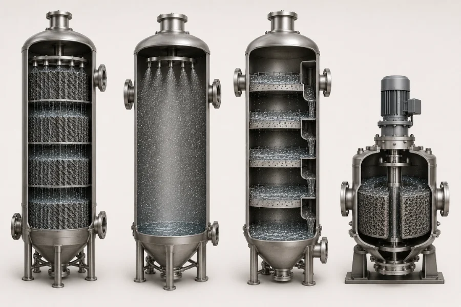
الأعمدة المعبأة والحشوات المنظمة
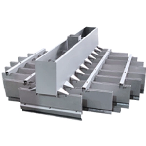
تعمل الملامسات المعبأة على توزيع السائل على الأسطح الداخلية بينما يمر الهواء عبر قنوات تدفق مترابطة. وتُعد الحشوات المهيكلة خيارًا جذابًا عندما يتعين الجمع بين المساحة الفعالة الكبيرة وانخفاض الضغط المتحكم فيه وهندسة التدفق التي يمكن التنبؤ بها.
تظهر هذه المفاضلة عند زيادة عمق التعبئة أو كثافتها. فقد تؤدي زيادة المساحة إلى تحسين الامتصاص، لكن انخفاض الضغط والحساسية تجاه التوزيع غير المتكافئ قد يزدادان أيضًا.
لذلك، يتعين تقييم تصميم الموزع، وقابلية التبلل، وسرعة الغاز السطحية، وهندسة الحشوة، وهامش التصميم بشكل متكامل. وبالنسبة لأنظمة DAC الكبيرة التي تعتمد على المذيبات، يمكن أن يوفر التلامس المنظم توازنًا عمليًّا بين أداء نقل الكتلة والثقة في توسيع نطاق العملية.
موصلات الرش
تقوم أنظمة الرش بتوزيع قطرات المذيبات في مساحة غازية مفتوحة نسبيًا. ويمكن أن تكون مقاومة التدفق المنخفضة لهذه الأنظمة مفيدة في الحالات التي تشكل فيها الطاقة اللازمة لتحريك الهواء قيدًا رئيسيًّا في العملية.
ويتمثل التنازل في انخفاض المساحة الحجمية للواجهة بين الطبقات مقارنةً بالمعدات ذات التعبئة الكثيفة. وتصبح عوامل مثل حجم القطرات، وتغطية الرش، ووقت البقاء، والانجراف، وأبعاد المعدات ذات أهمية كبيرة.
وهذا يجعل التلامس بالرش أمراً ذا أهمية خاصة عندما يكون تقليل استهلاك الطاقة في المروحة أكثر أهمية من تقليل الحجم المادي للممتص.
أعمدة الصواني
تُحدث أعمدة الصواني تلامسًا تدريجيًّا بين الغاز والسائل، وتستند في المعالجة الكيميائية التقليدية إلى أساليب تصميم هيدروديناميكية راسخة.
أما بالنسبة لنظام DAC، فإن انخفاض الضغط عبر المراحل المتعددة وانخفاض المساحة النوعية للواجهة بين الطبقات يمكن أن يشكلا عائقين عندما يتعين معالجة كميات هائلة جدًّا من الهواء المحيط.
قد تظل أنظمة الصواني مناسبة في الحالات التي تبرر فيها مرونة معالجة السوائل أو نطاق تشغيلي معين إجراء التلامس على مراحل، ولكن لا ينبغي اختيارها لمجرد أن هذه التقنية مألوفة.
الأسرة المعبأة الدوارة والمكثفات المكثفة
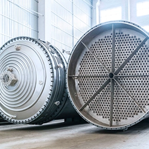
تستخدم الأسرة المعبأة الدوارة التسارع الطرد المركزي لتوليد أغشية رقيقة وقطرات وواجهات تلامس تتجدد بسرعة. ويمكن أن يؤدي تكثيف العملية الناتج عن ذلك إلى زيادة انتقال الكتلة الحجمي وتقليل المساحة التي تشغلها المعدات.
ويصاحب التصميم المدمج مجموعة أخرى من الاعتبارات الهندسية، وهي: الطاقة الدورانية، والتعقيد الميكانيكي، والصيانة، ومعايير التوسع، والتعامل مع تدفقات الهواء الكبيرة.
وبالتالي، يصبح المُتعاقد المُكثف خيارًا جذابًا عندما يكون الحجم أو نقل الحجم هو القيد الرئيسي — وليس تلقائيًا كلما كانت هناك حاجة إلى أعلى معدل ممكن لنقل الكتلة.
مصفوفة الاختيار الهندسية لمفاتيح DAC
لا يوجد ملامس غاز-سائل يُعتبر الأمثل بشكل عام. فالتركيب المفضل يتغير وفقًا للقيود السائدة في العملية.
| الموصل الكهربائي | إمكانية نقل الكتلة | انخفاض الضغط في الجانب الجوي | البصمة البيئية | التعقيد | تعزيز الثقة | إشارة الاختيار النموذجية |
|---|---|---|---|---|---|---|
| التعبئة المهيكلة | عالية | منخفضة-متوسطة | معتدل | معتدل | عالية | عملية استخلاص الكربون المباشر (DAC) المتوازنة على نطاق واسع باستخدام المذيبات |
| الموصل الرشاشي | معتدل | منخفضة جداً | كبير | منخفضة-متوسطة | عالية | عملية حساسة لطاقة المروحة |
| عمود الصواني | معتدل | متوسط-عالي | معتدل | معتدل | عالية | مرونة معالجة السوائل |
| الطبقة المعبأة الدوارة | عالية جداً | يعتمد على النظام | صغير | عالية | قيد التطوير | تكثيف العمليات المدمجة |
ينبغي استخدام الجدول كأداة تقييم أولي وليس كتصنيف شامل. فقد لا يؤدي التصميم المُحسَّن لتقليل المساحة المطلوبة إلى تقليل استهلاك الطاقة إلى أدنى حد، في حين أن المُوصِّل الذي يتميز بانخفاض كبير في انخفاض الضغط قد يتطلب حجمًا أكبر من المعدات.
من تصميم المفهوم إلى اختيار الحلول الهندسية
تبدأ عملية الاختيار العملية بالنظر إلى مهمة التجميع ونظام المذيبات أولاً، بدلاً من التركيز على نوع المعدات المفضل.
تحديد نطاق العملية
تحديد مهمة إزالة ثاني أكسيد الكربون، والظروف المحيطة، والهدف من عملية التقاط الغاز، ومعدل تدفق الهواء، وخصائص المذيب. وينبغي أخذ التغيرات في درجة الحرارة والرطوبة في الاعتبار، لأنها قد تؤثر على سلوك الامتصاص ونطاق التشغيل.
ومن ثم يمكن ترجمة متطلبات نقل الكتلة إلى المساحة الفعالة، ووقت التلامس، وحمولة السائل، والسرعة السطحية المسموح بها للغاز.
تحديد ميزانية انخفاض الضغط
قبل تحديد الشكل الهندسي للموصل بشكل نهائي، يجب تحديد مقدار انخفاض الضغط الذي يمكن أن تتحمله العملية.
وهذا يفرض على التصميم أن يكون مترابطًا:
معدل تدفق الهواء → مساحة المقطع العرضي → سرعة الغاز → ΔP → طاقة المروحة
إن المُوصِّل الذي يحقق هدف الامتصاص ولكنه يتجاوز ميزانية الطاقة المخصصة لحركة الهواء لا يُعد حلاً مُحسَّنًا لتقنية DAC.
فحص المقوم والتحقق من صلاحيته
أصبح من الممكن الآن مقارنة الحشوات وأنظمة الرش والمعدات المرحلية والموصلات المعززة وفقًا لنفس المتطلبات.
ينبغي أن يشمل التقييم التفصيلي توزيع السائل، والتبلل، والانجراف، وهامش الغمر، والتوجيه، وانخفاض الضغط، والحساسية تجاه التغيرات في أحمال الغاز والسائل. وتحدد هذه المتغيرات الهيدروديناميكية ما إذا كان الأداء النظري للممتص سيصمد في ظل ظروف التشغيل الفعلية.
التحقق من الصلاحية على نطاق تجريبي
ينبغي أن يقتصر الاختبار التجريبي على قياس كفاءة إزالة ثاني أكسيد الكربون فحسب.
إن سلوك انخفاض الضغط، واستغلال مساحة نقل الكتلة، ودوران المذيب، وأداء الموزع، والتآكل، والترسيب، والتلوث، والاستجابة للظروف البيئية الواقعية، كلها عوامل ذات صلة بالتوسع إلى النطاق التجاري.
الهدف ليس مجرد إثبات حدوث امتصاص ثاني أكسيد الكربون، بل هو تحديد ما إذا كان يظل نقل الكتلة، والطلب على الطاقة، وسلوك المواد، وقابلية التحكم في العمليات قابلاً للتكرار على المستوى التالي.
لماذا يمكن أن يؤدي التوسع إلى تغيير أفضل مقاول
يمكن لبيانات الامتصاص المختبرية تحديد تركيبات واعدة من المذيبات وأجهزة التلامس، لكن زيادة أبعاد المعدات تؤدي إلى تغيير البيئة الهيدروديناميكية.
قد تؤدي مساحات التدفق الأكبر إلى زيادة صعوبة الحفاظ على توزيع متجانس للسائل والغاز. وقد تؤدي الاختلافات المحلية في السرعة، والتبليل غير الكامل، وتكوّن القنوات، وتقلبات انخفاض الضغط إلى انخفاض الأداء الفعلي حتى في حالة بقاء المواصفات الاسمية للحشوة دون تغيير.
ومن المسارات الشائعة للتوسع ما يلي:
كلما زاد حجم الموصل → زادت صعوبة التوزيع → تباين الترطيب → انخفاض المساحة الفعالة → انحراف أداء الالتقاط عن التوقعات
ولهذا السبب، فإن الحفاظ على نفس المساحة السطحية الاسمية لكل وحدة حجم لا يُعد معيارًا كافيًا لتوسيع نطاق العملية.
كما أن حملات التشغيل الطويلة يمكن أن تكشف عن مشكلات قد تفوتها التجارب القصيرة، مثل: تدهور المذيبات، والترسيب، والتآكل، وانسداد الموزع، وتكوّن الرذاذ، والتلوث، والتغيرات الموسمية في الظروف البيئية المحيطة.
وبالتالي، فإن التوسع الصناعي يتطلب نطاقًا تشغيليًّا بدلاً من نقطة تصميم واحدة. وينبغي أن تظل معدلات الالتقاط، وانخفاض الضغط، ونسبة L/G، وسرعة الغاز، وحالة المذيب، والاستقرار الهيدروديناميكي في مستويات مقبولة عبر نطاق التباين التشغيلي الواقعي.
منطق عملي لاختيار موصلات DAC
يمكن أن تكشف إشارات العملية عن القيود الهندسية التي تستحق الاهتمام قبل إضافة معدات إضافية.
| إشارة العملية | التشخيص الهندسي المحتمل | التوجيه الهندسي |
|---|---|---|
| مساحة تعبئة كبيرة، لكن تحسنًا ضعيفًا في كفاءة التقاط الجسيمات | سوء استغلال المساحة أو سوء توزيعها | تحقق من الترطيب والتوزيع |
| ارتفعت مبيعات «كابتشر»، لكن طلب المعجبين زاد بشكل حاد | أصبحت ميزانية انخفاض الضغط عاملاً مقيداً | تقليل المقاومة على جانب الغاز |
| لا يؤدي ارتفاع نسبة L/G إلا إلى تحسن طفيف في القدرة على التقاط الأهداف | قد لا يكون الإمداد بالسائل هو العامل المحدد لعملية النقل بعد الآن | إعادة تقييم الحركية والمساحة الفعالة |
| تصبح البصمة البيئية القيد الرئيسي | نقل حجمي غير كافٍ | تقييم الاتصال المنظم أو المكثف |
| من المتوقع حدوث ترسبات أو تكوين مواد صلبة | مخاطر قابلية الصيانة | فكر في استخدام هندسة أكثر انفتاحًا |
| تسود مخاطر التوسع التجاري | الريبة الهيدروديناميكية | إعطاء الأولوية للتحقق التجريبي وسلوك التدفق المثبت |
وتعزز هذه المؤشرات المبدأ الهندسي الأساسي الذي مفاده أن تغيير الملامس لا يقتصر على نقل الكتلة فحسب، بل يمكن أن يؤثر أيضًا على طاقة المروحة، ووظيفة الضخ، ومخزون السوائل، والمساحة المطلوبة، وسهولة الصيانة، وتكامل نظام إعادة التوليد.
تصميم المقوم كجزء من عملية DAC
تقع معدات التلامس بين الغاز والسائل في مجال يجمع بين كيمياء المذيبات وتصميم العمليات الصناعية. ويؤثر أداء هذه المعدات على كمية الهواء التي يجب نقلها، وكمية المذيب التي يجب تدويرها، وحجم جهاز الامتصاص، ومدى استقرار تشغيل العملية.
الأفضل DAC وبالتالي، فإن المُوصل ليس بالضرورة الجهاز الذي يتمتع بأعلى معامل لنقل الكتلة. بل إن التكوين هو الذي يحافظ على ما يكفي من أداء امتصاص ثاني أكسيد الكربون في ظل انخفاض مقبول في الضغط، ومستوى مقبول في الطلب على الطاقة، وحجم مقبول للمعدات، ومخاطر تشغيلية مقبولة.
بالنسبة لتقنيات DAC التي تنتقل من مرحلة تطوير المفهوم إلى مرحلة التنفيذ التجريبي والتطبيق التجاري، ينبغي أن يتم اختيار المقاولين بشكل متكامل مع عمليات تجديد المذيبات، والمرافق، والمواد، والتحكم في العمليات، وتصميم المصنع.
دودجن تتعامل مع هذا التحدي باعتباره مشكلة تتعلق بهندسة العمليات والتصنيع — حيث تربط بين الامتصاص التفاعلي، والهيدروديناميكا، وتكثيف العمليات، وتكوين المعدات، والتحقق التجريبي، وتوسيع نطاق العمليات، بدلاً من الاكتفاء بتحسين جهاز التلامس الهوائي بمعزل عن العوامل الأخرى.
السؤال الهندسي الأخير لا يقتصر على مجرد،, أي من المقومات يلتقط أكبر كمية من ثاني أكسيد الكربون؟
وهو:
ما هي بنية التلامس التي يمكنها تحقيق الأداء المطلوب لنقل ثاني أكسيد الكربون عبر نطاق التشغيل الصناعي، دون أن يصبح استهلاك الطاقة أو حجم المعدات أو تعقيد العمليات عائقًا جديدًا؟