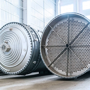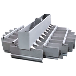
One of the most critical steps in المبادل الحراري selection is estimating the heat duty correctly. If the heat duty is overestimated, the exchanger becomes oversized, increasing both capital cost and footprint. If it is underestimated, the required process conditions may not be achieved, and modifications after installation can be costly.
This article focuses on three practical questions: how to calculate heat duty, how to estimate heat transfer area, and how shell-and-tube and plate heat exchangers differ in equipment selection.
Heat Duty Calculation: Start with the Fluid and Operating Conditions
Heat duty calculations are fundamentally based on an energy balance.
For a single-phase fluid:
Q = m × Cp × ΔT
The equation is straightforward, but several details require careful attention in engineering practice.
The first is the selection of Cp, the specific heat capacity. It is common to take a single value directly from a handbook, but for organic solvents and mixed gases, Cp may vary significantly with temperature. When the temperature difference exceeds about 50°C, it is generally more appropriate to use a value corresponding to the average inlet and outlet temperature, or to account for its temperature dependence more accurately.
The second consideration is phase change. For condensation or evaporation:
Q = m × r
حيث r is the latent heat. The latent heat value must be selected for the actual operating conditions. In many cases, sensible and latent heat must both be included. For example, in a steam-heated process, the steam side releases latent heat during condensation, while the process stream absorbs sensible heat as its temperature increases.
The third consideration is heat loss. In preliminary engineering calculations, heat loss is sometimes estimated at approximately 5%–10% of the total heat duty. The higher end of the range may be appropriate when insulation is poor or ambient temperatures are low.
If phase change occurs on both sides—for example, steam condensing on one side while a process fluid boils on the other—the energy balance should be checked independently from both sides to ensure consistency.
Heat Transfer Area Estimation: The Overall Heat Transfer Coefficient Is Critical
A commonly used equation for preliminary heat transfer area estimation is:
A = Q / (K × ΔTm)
حيث:
- A = heat transfer area
- Q = heat duty
- K = overall heat transfer coefficient
- ΔTm = logarithmic mean temperature difference, or LMTD
The LMTD calculation itself is not complicated, but the exchanger flow arrangement must be identified correctly. Countercurrent and cocurrent flow can produce very different effective temperature driving forces.
If one side undergoes phase change at approximately constant temperature, the LMTD is determined from the temperature differences between that constant-temperature stream and the inlet and outlet temperatures of the other stream. If both streams change temperature, the standard LMTD equation is used.
Selecting the overall heat transfer coefficient K usually requires the most engineering judgment.
For shell-and-tube heat exchangers, typical preliminary values may be approximately:
- Water-to-water: 800–1,500 W/(m²·°C)
- Organic solvent-to-water: 300–600 W/(m²·°C)
- Gas-to-gas: 30–60 W/(m²·°C)
Plate heat exchangers often achieve considerably higher heat transfer coefficients because their narrow channels and corrugated plates promote strong turbulence. For water-to-water service, K values may reach approximately 3,000–5,000 W/(m²·°C).
However, K is influenced not only by the fluids but also by velocity, viscosity, fouling resistance, exchanger geometry, and construction materials. In preliminary design, handbook ranges can be used as a starting point, but they should be adjusted according to actual process conditions and verified during detailed equipment sizing.
Example: Heat Exchanger Selection for Toluene Cooling
Consider a process that requires cooling toluene from 80°C to 40°C at a flow rate of 10 m³/h.
Assume:
- Toluene density: 870 kg/m³
- Toluene specific heat capacity, Cp: 1.8 kJ/(kg·°C) at an average temperature of approximately 60°C
- Cooling water inlet temperature: 30°C
- Cooling water outlet temperature: 38°C
First, calculate the mass flow rate:
m = 10 × 870 / 3,600 ≈ 2.42 kg/s
The heat duty is:
Q = m × Cp × ΔT
Q = 2.42 × 1.8 × (80 − 40) ≈ 174.2 kW
Assuming a 5% design allowance:
Qdesign = 174.2 × 1.05 ≈ 183 kW
Next, calculate the LMTD.
For countercurrent flow:
Toluene: 80°C → 40°C
Cooling water: 30°C → 38°C
لذلك:
Δt1 = 80 − 38 = 42°C
Δt2 = 40 − 30 = 10°C
Then:
ΔTm = (42 − 10) / ln(42 / 10) ≈ 22.3°C
For comparison, with cocurrent flow:
Δt1 = 80 − 30 = 50°C
Δt2 = 40 − 38 = 2°C
The LMTD would be only about 14.9°C, showing why countercurrent flow generally provides a more effective temperature driving force for this service.
Shell-and-Tube Heat Exchanger
Assume:
K = 400 W/(m²·°C)
for preliminary toluene-water service.
Then:
A = 183,000 / (400 × 22.3) ≈ 20.5 m²
With a 10% design margin:
Adesign ≈ 22.6 m²
A shell-and-tube exchanger with approximately 25 m² of heat transfer area could therefore be considered for preliminary selection.
Plate Heat Exchanger
Assume:
K = 2,000 W/(m²·°C)
Then:
A = 183,000 / (2,000 × 22.3) ≈ 4.1 m²
With a 20% design margin:
Adesign ≈ 4.9 m²
A plate heat exchanger with approximately 5 m² of effective heat transfer area could therefore be considered at the preliminary design stage.
The two options can be summarized as follows:
| Item | Shell-and-Tube | Plate Heat Exchanger |
|---|---|---|
| Calculated area | 20.5 m² | 4.1 m² |
| Preliminary design area | ~25 m² | ~5 m² |
| البصمة البيئية | أكبر | أصغر |
| الصيانة | Tube bundle can be accessed depending on design | Plates normally need to be opened |
| Temperature/pressure capability | Suitable for demanding high-temperature and high-pressure services | More dependent on plate and gasket design |
| حساسية التلوث | Generally lower | Generally higher in narrow channels |
Selection Comparison: Shell-and-Tube or Plate Heat Exchanger?
From the standpoint of heat transfer area alone, plate heat exchangers are clearly more compact. However, exchanger selection should never be based on area alone.
Shell-and-tube heat exchangers are widely used for high-temperature, high-pressure, and demanding process services. Their allowable pressure can vary significantly depending on mechanical design, materials, code requirements, and construction.
Gasketed plate heat exchangers are more constrained by gasket material, plate design, operating temperature, and pressure. Conventional designs are commonly used in moderate-temperature and moderate-pressure services, while specialized plate technologies can extend these operating limits.
Fluid characteristics are equally important. If the process stream contains suspended solids or has a strong tendency to foul, the narrow channels of a plate heat exchanger may be more susceptible to blockage. A shell-and-tube exchanger may therefore provide greater operating robustness.
Maintenance philosophy also differs. Many shell-and-tube designs allow mechanical cleaning of the tubes or removal of the tube bundle. Plate heat exchangers require the plate pack to be opened for inspection and cleaning, but they offer an important advantage: heat transfer area can often be adjusted by adding or removing plates.
From a cost perspective, plate heat exchangers can be economical because of their high heat transfer efficiency and compact size. However, gasket replacement and plate maintenance should be considered in lifecycle cost evaluations.
Shell-and-tube exchangers may involve higher initial investment and larger installation space, but they are often preferred for severe operating conditions and long service life.
As a practical guideline, a plate heat exchanger may be preferred when the fluids are clean, operating temperature and pressure are moderate, and flexibility in heat transfer area is valuable. Shell-and-tube equipment is generally more suitable for dirty, particulate-containing, high-temperature, or high-pressure services.
Pressure drop must also be checked carefully. Plate exchangers often operate with relatively high pressure drops to achieve strong turbulence and high heat transfer coefficients. If the available system pressure drop is limited, this can become a decisive selection factor.
Important Factors That Are Often Overlooked
1. Fouling Resistance
Fouling resistance must be incorporated into thermal design.
For preliminary shell-and-tube calculations, typical fouling resistance assumptions may fall in ranges such as:
- Water side: approximately 0.0002–0.0006 m²·°C/W
- Organic fluid side: approximately 0.0001–0.0004 m²·°C/W
Actual values should be selected according to fluid quality, operating history, industry practice, and applicable design standards.
Plate heat exchangers often experience lower fouling tendencies because of higher channel velocities and turbulence, but fouling should never be ignored. If fouling resistance is underestimated, exchanger performance may decline significantly after extended operation.
2. Pressure Drop Verification
Thermal sizing is only part of exchanger design. Pressure drop must also be verified.
For shell-and-tube exchangers, both tube-side and shell-side pressure drops must be checked. Plate exchangers use different hydraulic correlations, and manufacturers commonly provide dedicated sizing software.
Excessive pressure drop increases pumping energy requirements and may even require changes to pump selection or system design.
3. Material Selection
Materials of construction should be selected according to the actual chemical environment.
Toluene itself is generally compatible with carbon steel under many conventional process conditions, but the presence of corrosive contaminants can change the material requirement.
Common shell-and-tube materials include:
- Carbon steel
- الفولاذ المقاوم للصدأ 304
- الفولاذ المقاوم للصدأ 316L
Common plate materials include:
- الفولاذ المقاوم للصدأ 304
- الفولاذ المقاوم للصدأ 316L
- Titanium for seawater and other highly corrosive services
Material selection directly affects both equipment cost and service life, so it should be based on corrosion data and actual process composition rather than purchase price alone.
4. Operating Flexibility
Plate heat exchangers offer an advantage when future duty changes are expected because heat transfer area can often be modified by adding or removing plates.
Changing the area of a shell-and-tube exchanger is considerably more difficult. For processes with wide operating ranges or uncertain future capacity requirements, this flexibility can be an important consideration.
اعتبارات ختامية
Heat exchanger selection cannot be solved by a single formula.
A reliable design requires an accurate heat duty, a realistic overall heat transfer coefficient, sufficient heat transfer area and design margin, and an equipment configuration that matches the actual fluid properties, temperature, pressure, fouling tendency, allowable pressure drop, and maintenance requirements.
In the example above, the preliminary calculation gives approximately 25 m² for a shell-and-tube exchanger and 5 m² for a plate heat exchanger. However, the smaller area alone does not make the plate exchanger the better choice. Fluid cleanliness, pressure, temperature, fouling behavior, gasket compatibility, and hydraulic limitations must all be verified first.
For actual engineering projects, preliminary hand calculations should therefore be followed by detailed thermal and hydraulic rating using reliable design methods or manufacturer sizing software before the final exchanger is selected.