Structured packing can provide high mass-transfer efficiency with relatively low pressure drop, but neither characteristic alone determines whether a packed column can operate reliably at industrial throughput.
Structured packing hydraulic design must consider how gas load, liquid load, packing geometry, fluid properties, and distribution interact as throughput changes. A column may satisfy its theoretical separation requirement yet operate too close to loading or flooding, leaving insufficient margin for feed variation, turndown, foaming, or changing physical properties.
Flooding point, pressure drop, and capacity should therefore be evaluated as parts of one hydraulic operating envelope rather than as independent design calculations.

Hydraulic Capacity Is a System Property, Not a Packing Rating
Structured packing has inherent geometric characteristics, including specific surface area, void fraction, corrugation geometry, channel dimensions, and surface properties. These parameters influence hydraulic resistance and available gas-liquid contact area.
They do not, however, define the achievable capacity of an industrial column by themselves.
Actual hydraulic performance also depends on:
- vapor and liquid densities
- viscosity and surface tension
- gas and liquid flow rates
- operating pressure and temperature
- liquid and gas distribution
- packing bed configuration
- distributor and redistributor design
- foaming or fouling tendency
- process variability
This distinction becomes increasingly important during scale-up. A packing that performs predictably under controlled conditions may behave differently in a larger column where distribution quality and local hydraulic nonuniformity become more influential.
For commercial structured packing hydraulic design, the relevant limit is therefore the maximum sustainable throughput of the complete mass-transfer section while maintaining acceptable pressure drop, wetting, separation efficiency, and operating margin.
Nominal packing capacity ≠ achievable column capacity.
Gas and Liquid Loads Define the Hydraulic Operating Window
Gas velocity is a primary driver of pressure drop in countercurrent packed columns. Gas loading is often represented by the F-factor:
F = u × √ρᵥ
where u is superficial gas velocity and ρᵥ is vapor density.
This representation is more useful than gas velocity alone when comparing operating conditions because vapor density changes with pressure, temperature, and composition.
Liquid loading must be considered simultaneously. As liquid flow increases, more void space is occupied by the liquid phase, liquid holdup rises, and interaction between countercurrent gas and liquid becomes stronger.
The useful operating region therefore cannot be defined by a single maximum gas-flow number.
At low liquid load, incomplete wetting may prevent the available packing surface from being used effectively. At excessive gas and liquid loads, hydraulic interaction intensifies until the system approaches loading and eventually flooding.
Structured packing hydraulic design must establish a stable region between these lower and upper limits.

Pressure Drop Shows How Hydraulic Margin Is Disappearing
Pressure drop is not merely an energy-consumption parameter. Its behavior can reveal changes in gas-liquid interaction inside the packing.
At moderate loading, gas moves upward through the packing channels while liquid drains downward under gravity. Pressure drop remains relatively predictable as gas throughput increases.
At higher gas velocity, upward gas momentum increasingly interferes with downward liquid flow.
The hydraulic progression can be viewed as:
Stable countercurrent flow → increasing gas-liquid interaction → loading → rapid liquid holdup growth → flooding
Near the loading region, liquid drainage becomes increasingly restricted. Additional liquid remains inside the packing, reducing the effective free area available for gas flow.
This creates a reinforcing hydraulic mechanism:
Higher gas load → greater liquid holdup → lower available flow area → higher gas resistance → further liquid accumulation
Pressure drop then rises much faster than it did in the stable operating region.
A nonlinear increase in differential pressure is therefore an important indication that hydraulic operating margin is narrowing.
Local Flooding Can Occur Before the Predicted Flood Point
Flooding is commonly described as the condition in which upward gas flow severely restricts normal downward liquid flow. For industrial design, however, treating flooding as one exact gas velocity can be misleading.
Flow through a commercial packed bed is not perfectly uniform.
Poor liquid distribution can create locally overloaded zones while other areas remain under-irrigated. These overloaded regions may develop high liquid holdup and excessive hydraulic resistance before the cross-sectional average reaches the predicted flooding condition.
The practical distinction is important:
Local hydraulic limitation can precede nominal column flooding.
Possible operating signals include:
- differential pressure increasing faster than expected
- unstable liquid behavior
- increased entrainment
- declining separation performance
- fluctuating temperature or composition profiles
- loss of process controllability
Flooding correlations and packing performance data should therefore define a design boundary, not be treated as an absolute guarantee of stable operation.
Liquid Distribution Can Determine the Real Capacity Limit
Structured packing relies on reasonably uniform irrigation to develop effective gas-liquid contact.
If excessive liquid enters one region while another receives insufficient irrigation, the average liquid load can still appear acceptable even though local hydraulic conditions are unfavorable.
The overloaded region develops greater liquid holdup and reduced gas-flow area, potentially causing premature loading. The under-irrigated region creates a different loss because part of the installed packing contributes less effectively to mass transfer.
For this reason:
Installed packing area ≠ wetted area ≠ effective mass-transfer area
Increasing specific surface area alone cannot correct poor distribution.
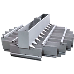
Distributor design, drip-point arrangement, distributor levelness, liquid rate, packing installation, and redistribution between sufficiently long beds can all affect achievable column performance.
The issue becomes increasingly significant as column diameter grows because small distribution imperfections can translate into substantial differences in local flow.
Packing Surface Area Creates a Capacity-Efficiency Trade-Off
Higher specific surface area can increase potential gas-liquid contact area and improve separation efficiency. It also generally creates a more restrictive hydraulic environment.
The resulting trade-off is fundamental to structured packing selection.
| Packing Direction | Mass-Transfer Potential | Hydraulic Capacity | Pressure-Drop Tendency |
|---|---|---|---|
| Lower specific surface area | Moderate | Higher | Lower |
| Medium specific surface area | High | High to moderate | Moderate |
| Higher specific surface area | Higher | Lower | Higher |
| Dense wire-mesh structures | Very high in suitable service | More constrained | More sensitive to loading |
A high-throughput absorber, for example, may benefit more from hydraulic capacity than from maximizing theoretical separation efficiency per meter. A high-purity distillation service may justify additional surface area when separation performance has greater economic value.
Pressure drop becomes especially important in vacuum service because hydraulic resistance contributes to the pressure profile through the column and can affect the separation environment.
The engineering target is sufficient effective mass-transfer area at an acceptable hydraulic cost.
Packing Geometry Matters Beyond Specific Surface Area
Two structured packings with similar nominal surface areas can exhibit different hydraulic behavior.
Corrugation angle, channel geometry, crimp dimensions, void structure, intersections, and surface treatment influence gas-flow resistance, liquid spreading, wetting, and ultimately flooding behavior.
More open geometries generally favor hydraulic capacity. Denser structures may provide greater interfacial area but impose higher resistance or a narrower operating window.
Packing selection should therefore not be reduced to a single value in m²/m³.
The geometry must be evaluated against the actual gas and liquid loads, physical properties, allowable pressure drop, separation duty, and expected operating range.
Percentage of Flooding Is Not the Same as Operational Risk
Packed columns are normally designed below their predicted flood point. A design region around 70%–80% of calculated flooding is frequently used as an initial engineering reference, but it should not become an automatic rule for every service.
Consider two columns operating at the same nominal percentage of flooding.
One handles a clean system with stable physical properties and limited feed variation. The other experiences composition changes, foaming tendency, fouling risk, or significant liquid-rate fluctuations.
Their calculated hydraulic margin may look identical, while their operational risk is very different.
The required margin should therefore reflect uncertainty and process behavior as well as predicted flooding capacity.
Systems with greater variability may justify a more conservative operating point to preserve continuous production and controllability.
Capacity Optimization Must Balance Diameter, Efficiency, and Stability
Higher gas loading can reduce the required column diameter for a given vapor throughput, potentially reducing vessel size and capital cost. Moving closer to flooding, however, reduces the margin available for process disturbances.
Increasing packing surface area introduces a similar trade-off. Separation potential may improve while hydraulic resistance increases.
| Design Direction | Potential Benefit | Engineering Trade-Off |
|---|---|---|
| Higher gas loading | Smaller column diameter | Reduced flooding margin |
| Higher packing area | Greater separation potential | Higher hydraulic resistance |
| Higher liquid load | Greater liquid-side throughput | Higher holdup and lower gas capacity |
| More open packing | Lower pressure drop | Potentially more packed height |
| Larger hydraulic margin | Greater operating stability | Potentially larger equipment |
The commercial optimum is determined by the interaction of column diameter, packed height, pressure drop, separation efficiency, operating flexibility, and process stability.
This is a process-system optimization problem rather than a packing-selection problem.
Minimum Hydraulic Load Defines the Other Side of the Envelope
Flooding establishes the upper hydraulic boundary, but reliable industrial operation also requires a credible lower boundary.
At very low liquid rates, complete wetting becomes more difficult. Portions of the installed surface may become poorly irrigated, reducing effective interfacial area and mass-transfer performance.
This matters for plants requiring significant turndown.
A column optimized only for nameplate capacity may lose separation performance during startup, partial-load production, campaign transitions, or downstream production constraints.
The hydraulic envelope should therefore include:
Minimum effective contacting load → stable operating region → loading → flooding
Evaluating both boundaries gives operators a more useful production window than a single maximum-capacity value.
Operating Signals Can Reveal the Limiting Hydraulic Mechanism
Calculated capacity should ultimately be connected to observable process behavior. Differential pressure, separation performance, and load response can help identify which hydraulic mechanism is becoming limiting.
| Operating Signal | Likely Hydraulic Issue | Engineering Response |
|---|---|---|
| ΔP rises faster than expected with throughput | Loading or increasing liquid holdup | Review gas load, liquid rate, and hydraulic margin |
| Separation declines while average load appears acceptable | Liquid maldistribution | Evaluate distributor performance and irrigation uniformity |
| Instability develops below predicted flooding | Local hydraulic limitation | Check distribution, packing condition, and local loading |
| Performance deteriorates during turndown | Incomplete wetting | Review minimum irrigation requirements |
| Commercial column underperforms pilot results | Scale-up distribution effect | Reassess gas/liquid distribution and redistribution strategy |
This diagnostic approach is useful because the same apparent capacity loss can arise from different mechanisms.
Increasing column diameter or changing packing does not solve every hydraulic problem. If maldistribution is the actual constraint, the engineering response may lie in distributor design rather than packing capacity.
Scale-Up Can Change the Hydraulic Bottleneck
Scaling a packed column from laboratory or pilot operation to commercial diameter requires more than maintaining the same F-factor.
Larger columns introduce additional sensitivity to:
- liquid and gas distribution
- distributor fabrication tolerances
- packing installation
- wall effects
- redistribution strategy
- process variability
- differential-pressure monitoring
Cross-sectional averages can therefore hide local conditions that become important at commercial scale.
Pilot validation is particularly useful for unfamiliar physical properties, difficult wetting, foaming systems, unusual pressure conditions, high viscosity, or services where reliable industrial hydraulic data are limited.
A practical scale-up sequence is:
Process properties → hydraulic model → packing selection → distributor design → pilot validation where required → commercial hydraulic envelope → operating control strategy
Pilot work should establish more than whether the required separation can be achieved. It can help determine how pressure drop evolves with load, where hydraulic instability begins, whether liquid distribution remains effective, and what operating margin should be retained during commercialization.
A Practical Structured Packing Hydraulic Design Workflow
A commercial design can be organized into a concise engineering sequence.
1. Define the Process Envelope
Establish gas and liquid flow rates, compositions, pressure, temperature, separation targets, turndown, and expected variability.
2. Establish Relevant Fluid Properties
Evaluate density, viscosity, surface tension, and other service-specific behavior affecting hydraulics and wetting.
3. Screen Packing Geometry
Compare surface area, void structure, corrugation geometry, material, expected separation performance, pressure drop, and hydraulic capacity.
4. Establish Loading and Flooding Boundaries
Use appropriate correlations, validated vendor data, process models, or experimental information to estimate the upper hydraulic limit.
5. Select an Operating Margin
Account for feed variability, fouling, foaming, control requirements, and production continuity rather than applying one flooding percentage mechanically.
6. Evaluate Distribution and Pressure Drop
Assess hydraulic behavior across the expected operating range and determine whether local distribution could become limiting.
7. Validate Scale-Up Risk
Where uncertainty is significant, use pilot testing and process modelling to reduce the gap between calculated and commercial behavior.
8. Define the Commercial Operating Envelope
Translate hydraulic analysis into practical gas-flow, liquid-flow, differential-pressure, turndown, and control limits.
This final step converts packing performance data into an industrial operating strategy.
From Hydraulic Capacity to Reliable Industrial Separation
The central question in structured packing hydraulic design is not how close a column can operate to its theoretical flooding point. It is how much throughput can be processed while preserving predictable pressure drop, effective gas-liquid contacting, separation performance, and sufficient operating margin.
That requires flooding, liquid distribution, packing geometry, minimum irrigation, pressure drop, and process variability to be evaluated as one interacting system.
For DODGEN, this fits within a broader separation engineering workflow that can connect hydraulic evaluation and process modelling with pilot validation, internals integration, and pilot-to-commercial scale-up.
The result is not simply a structured packing specification. It is a defined industrial operating envelope designed around separation performance, capacity, controllability, and long-term process stability.