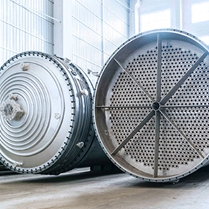
Liquid entrainment occurs when liquid droplets travel with the gas stream instead of being removed by a gas-liquid separator. Excessive carryover can contaminate downstream process streams, increase liquid loading on compressors and purification equipment, and compromise continuous operation.
The source determines the corrective action. Droplets may enter with the feed, form through gas-liquid interactions inside the vessel, or return to the gas stream after collection on internal surfaces. Effective optimization requires identifying the dominant mechanism, measuring carryover under defined conditions, and validating corrective actions against separation performance and pressure drop.
What Is Liquid Entrainment in a Gas-Liquid Separator?
Liquid entrainment is the transport of liquid droplets by a continuous gas phase. Three related terms describe different stages of the problem.
Primary Entrainment vs. Secondary Re-Entrainment
Primary entrainment occurs when liquid first enters the gas stream as dispersed droplets. Sources include upstream piping, inlet turbulence, and liquid surfaces exposed to gas shear inside the vessel.
Secondary re-entrainment occurs when previously collected liquid detaches from a wall, vane, mesh pad, or drainage surface and returns to the gas stream. Excessive gas shear, liquid accumulation, and restricted drainage can trigger this process.
The distinction matters because improving droplet capture will not necessarily solve a drainage problem. If collected liquid repeatedly detaches from internal surfaces, the separator can continue to experience high carryover despite effective initial capture.
Entrainment vs. Liquid Carryover
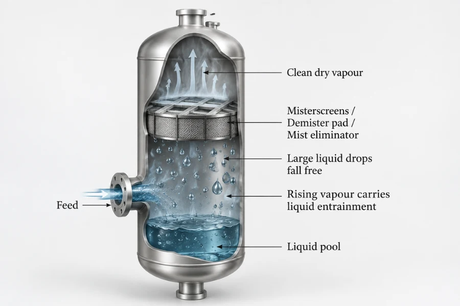
Liquid carryover is the liquid that leaves the separator with the outlet gas. It measures the overall separation outcome but does not identify the cause.
Carryover may result from fine droplets passing through the internals, localized high gas velocities, bypass flow, or re-entrainment of collected liquid. Outlet measurements establish the extent of the problem, while droplet-size data, pressure drop, liquid-level trends, and drainage measurements help identify its source.
Mechanisms That Cause Liquid Entrainment and Re-Entrainment
Inlet Shear and Droplet Breakup
High gas velocity, abrupt flow-direction changes, and local turbulence can break liquid structures into smaller droplets before they reach the main separation zone. Upstream elbows and inlet devices may also produce uneven liquid distribution or localized impingement.
A finer inlet droplet distribution can reduce gravity separation performance because smaller droplets generally settle more slowly relative to the gas. Comparing inlet and outlet droplet-size distributions, where representative measurements are available, helps determine whether the separator receives an excessive fine-droplet load or whether internal conditions contribute to the observed carryover.
The diagnosis should include upstream piping and inlet geometry rather than treating the separator vessel as an isolated component.
Free-Surface Wave Formation and Liquid Stripping
Gas flowing across a liquid surface creates aerodynamic shear. Under suitable conditions, interfacial waves develop and release droplets into the gas stream.
The onset depends on local gas velocity, gas and liquid densities, surface tension, liquid properties, liquid level, and vessel geometry. Changes in liquid level can alter the interaction between the inlet flow and the free surface, generating additional droplets even when total gas flow remains constant.
These droplets increase the liquid load entering the separation zone. If the mist eliminator receives more liquid than it can capture and drain under the operating conditions, outlet carryover may increase without any change in the internals themselves.
The onset of wave formation or droplet stripping cannot be defined by one critical gas velocity for all separators. It must be established for the relevant flow regime, fluid properties, liquid loading, and vessel geometry.
Re-Entrainment From Mist Eliminators and Drainage Surfaces
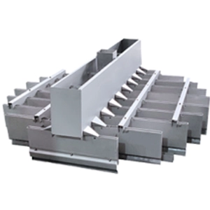
Mist eliminators capture droplets through inertial impaction, surface adhesion, and coalescence. The collected liquid must then drain away without being stripped back into the gas stream.
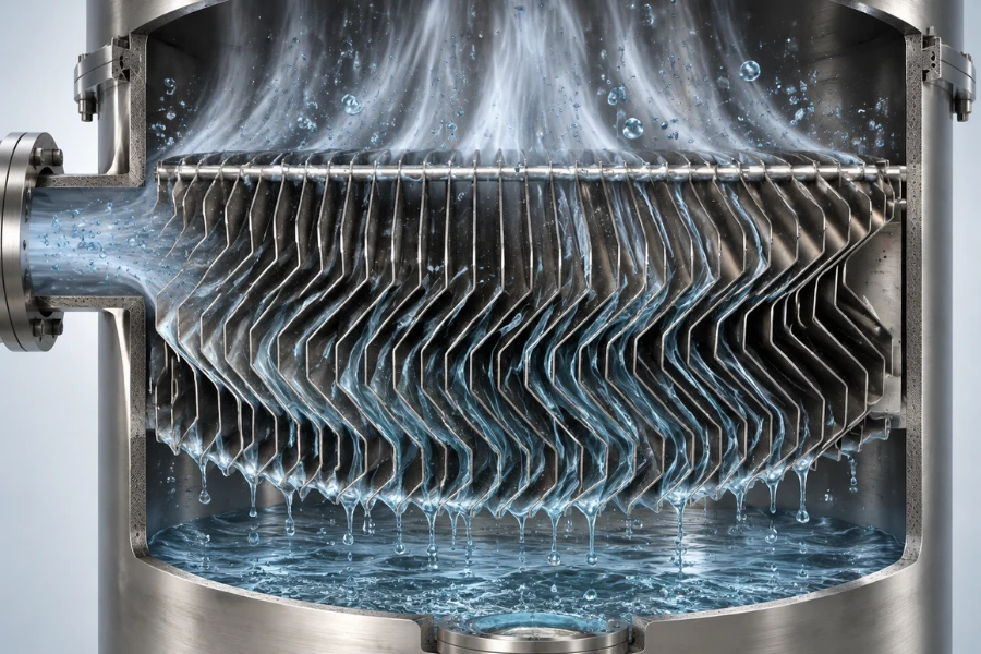
In vane-type mist eliminators, droplets form films on the plates and drain along the surfaces. In mesh pads, droplets collect on the wire network, coalesce, and form larger liquid bodies that must leave the collection zone.
As gas velocity increases, aerodynamic shear on the collected film increases. Film waves or local instabilities may develop, followed by liquid detachment and increased outlet carryover. Restricted drainage, excessive liquid loading, and uneven gas distribution can aggravate this sequence.
Experimental studies of wave-plate mist eliminators have investigated re-entrainment limits under specific gas and liquid flow conditions. Research on vane-type devices has also used liquid-film thickness measurements and force-balance analysis to investigate film breakup. These findings support evaluating film behavior and drainage capacity together, but they do not establish a universal critical velocity for every geometry or fluid system.
For further reading, see research on re-entrainment in wave-plate mist eliminators and research on re-entrainment in vane mist eliminators.
Gravity Separation and Droplet Transport
Gravity separation depends on the balance between droplet weight, buoyancy, aerodynamic drag, and the local gas-flow field. Droplets must reach a collection surface or liquid pool before leaving the vessel.
For a small, approximately spherical droplet at terminal settling conditions, the Stokes settling velocity is
[v_t=\frac{(\rho_l-\rho_g)gd^2}{18\mu_g}]
where (v_t) is the terminal settling velocity relative to the gas, (\rho_l) and (\rho_g) are liquid and gas densities, (g) is gravitational acceleration, (d) is droplet diameter, and (\mu_g) is gas dynamic viscosity.
This equation assumes a sufficiently low droplet Reynolds number for Stokes drag to apply, an approximately spherical droplet, and terminal settling conditions. Larger droplets or higher relative velocities may require an appropriate drag coefficient and force-balance calculation.
In upward gas flow, a droplet may fail to settle back into the liquid pool when the local upward gas velocity exceeds its downward terminal settling velocity relative to the gas. Actual carryover also depends on residence time, turbulence, flow direction, and internal geometry.
Under Stokes conditions, settling velocity varies with the square of droplet diameter. This explains why a shift toward smaller inlet droplets can increase carryover even when vessel geometry and average gas flow remain unchanged.
How to Measure Liquid Entrainment in a Gas-Liquid Separator
A meaningful entrainment test requires a defined measurement boundary, a consistent reference flow, and a method suited to the expected droplet sizes and liquid concentration. Without these controls, reported values may not be directly comparable.
Define the Test Boundary and Performance Metrics
Specify where liquid is measured, which liquid flow provides the reference, and whether the result is expressed as mass flow, volume flow, concentration, or a dimensionless fraction.
| Metric | Purpose |
|---|---|
| Liquid entrainment rate | Quantifies liquid crossing a defined boundary per unit time |
| Entrainment fraction | Expresses measured carryover relative to a specified reference liquid flow |
| Outlet liquid carryover | Measures liquid leaving with the gas on a defined mass or volume basis |
| Droplet-size distribution | Characterizes droplet sizes at a specified sampling location |
| 압력 강하 | Tracks hydraulic resistance across the separator or a defined component |
| Entrainment onset | Identifies the first reproducible occurrence of entrainment under a predefined criterion |
Pressure drop is a useful diagnostic variable, but it does not directly measure carryover. Similarly, a droplet-size distribution describes the population of droplets rather than the total liquid mass transported.
A mass-based entrainment fraction can be calculated as
[E_m=\frac{\dot m_c}{\dot m_r}\times100%]
where (\dot m_c) is the measured liquid carryover mass flow rate and (\dot m_r) is the reference liquid mass flow rate. If the reference is the inlet liquid feed, the result expresses carryover as a percentage of incoming liquid.
The denominator and measurement basis must remain consistent across tests. Mass-based and volume-based fractions are not directly interchangeable unless the conversion basis and relevant densities are established.
Design the Sampling System
Sampling can distort the measured droplet population. Liquid may deposit on tubing walls, coalesce, evaporate, or undergo additional condensation between the separator outlet and the measurement point.
Document the sampling location, probe and line arrangement, operating pressure and temperature, measurement range, detection limit, and sampling duration. Select a collection method or droplet-sizing instrument suited to the expected concentration and size range.
A collection-based method can quantify liquid when recovery is reliable. Droplet-sizing instruments can characterize the distribution but may not measure total liquid mass directly. Where both quantities are important, use complementary methods and evaluate whether their results are consistent.
Establish a Controlled Test Matrix
A structured test matrix helps separate the effects of gas velocity from liquid loading. Establish a stable baseline, vary one principal factor at a time where practical, and record the variables needed to interpret each response.
| Test | Controlled or recorded variables | Main purpose |
|---|---|---|
| Gas-velocity scan | Gas flow, liquid load, liquid level, pressure drop, carryover | Identify carryover trends and possible re-entrainment onset |
| Liquid-load scan | Liquid feed, gas flow, drainage, carryover | Determine whether liquid handling or drainage limits performance |
| Repeatability test | Same operating point and sampling procedure | Quantify measurement and process variability |
| Before-and-after comparison | Same boundary, reference basis, and sampling method | Determine whether optimization produces a measurable improvement |
At each test point, confirm that the system has stabilized before collecting data. Record outlet carryover alongside pressure drop, liquid level, and drainage behavior. If transient operation is relevant, steady-state tests alone will not establish performance during those events.
Determine Re-Entrainment Onset
Define the onset criterion before testing. It may be a sustained increase in outlet carryover, a reproducible change in liquid-film behavior, or another measurable response that indicates the start of re-entrainment.
Increase gas velocity in controlled increments while maintaining the specified liquid load. Allow the system to stabilize at each point, then record carryover, pressure drop, liquid level, and drainage performance. Repeat representative conditions to determine whether the observed onset is reproducible.
If the system may exhibit hysteresis, also conduct a controlled downward-flow sequence. The recovery point during decreasing flow may differ from the onset during increasing flow because liquid has accumulated inside the internals.
Report the result as an onset condition for the tested geometry, fluid properties, liquid load, and detection method. The observed onset is not a universal design limit. Detection sensitivity also matters because an instrument with a higher detection limit may identify onset later than a more sensitive method.
Evaluate Measurement Uncertainty and Mass Balance
Carryover measurements may be affected by flow-meter accuracy, collected-liquid measurement, sampling losses, timing, instrument resolution, and process fluctuations. These uncertainties should be assessed before small performance changes are interpreted as meaningful.
For the mass-based entrainment fraction
[E_m=100\frac{\dot m_c}{\dot m_r}]
an approximate relative standard uncertainty is
[\frac{u(E_m)}{E_m}\approx\sqrt{\left(\frac{u(\dot m_c)}{\dot m_c}\right)^2+\left(\frac{u(\dot m_r)}{\dot m_r}\right)^2}]
where (u) denotes standard uncertainty. This approximation assumes independent measurements and sufficiently small relative errors. Correlated errors require a covariance term.
For example, if the relative standard uncertainties of the carryover and reference-flow measurements are 5% and 2%, respectively, the approximate relative standard uncertainty of the fraction is 5.4%. This is an illustrative calculation, not a specification for any particular instrument or separator.
The approximation is unsuitable for reporting reliable relative uncertainty when carryover approaches zero or falls below the measurement detection limit. In such cases, report the detection limit and use an appropriate absolute uncertainty or measurement interval.
Where practical, compare inlet liquid feed, collected liquid, and outlet carryover over the same time interval. Account for other liquid outlets and changes in internal liquid holdup. Poor mass-balance closure may indicate sampling losses, unmeasured accumulation, unstable operation, or measurement error. A mass balance should only be interpreted as a steady-state closure when the system is sufficiently stable and liquid accumulation has been accounted for.
How to Diagnose Re-Entrainment in Industrial Separators
Diagnosis should distinguish competing explanations rather than assign a cause from a single symptom.
| Observed symptom | Possible causes | Evidence and next check |
|---|---|---|
| Carryover rises with gas flow | Poor settling, local high velocity, or film stripping | Compare carryover and pressure-drop trends; investigate flow distribution and onset behavior |
| Carryover rises with liquid loading | Excessive inlet droplet load, liquid accumulation, or restricted drainage | Compare inlet feed, liquid level, drain flow, and outlet carryover |
| Pressure drop rises with carryover | Internal liquid accumulation, flooding, or restricted passages | Determine whether pressure drop rises before or alongside carryover; inspect drainage and sectional pressure drop |
| Carryover fluctuates with liquid level | Free-surface stripping, inlet interaction, or unstable level control | Align level, gas-flow, and carryover records by time |
| Fine droplets dominate the outlet | Fine inlet droplets, inadequate capture, or local bypass | Compare inlet and outlet size distributions where measurable; investigate flow distribution |
| Performance changes after a process modification | Changed fluid properties, operating regime, fouling, or flow conditions | Compare current operating data with the original design basis |
These symptoms are diagnostic clues rather than definitive proof. More than one mechanism may be active simultaneously.
Distinguish Capture Failure From Drainage Failure
Capture failure occurs when droplets pass through the separation zone without being collected. Drainage failure occurs when captured liquid cannot leave the internal surfaces at the required rate.
Investigate capture failure by examining the inlet droplet population, outlet size distribution, and flow-distribution evidence. Investigate drainage failure by comparing carryover with pressure drop, liquid level, drain flow, and evidence of liquid accumulation.
If carryover increases while drainage deteriorates and pressure drop rises, liquid accumulation or flooding becomes a stronger hypothesis. If carryover increases without a corresponding change in drainage or pressure drop, investigate inlet loading, fine-droplet penetration, and local bypass before modifying the drainage system.
Engineering Strategies to Reduce Entrainment
Optimization should follow the diagnosed mechanism. Each modification must be evaluated against outlet carryover, pressure drop, drainage performance, and the intended operating range.
Correct Excessive Initial Droplet Loading
When the inlet supplies excessive fine droplets, investigate upstream piping, inlet momentum, local liquid impact, and inlet-device geometry. A revised configuration may reduce harmful breakup or distribute the incoming phases more evenly.
If droplets originate from the free surface, examine local gas velocity, liquid level, and inlet-jet interaction. Changing operating conditions or internal geometry may reduce droplet formation, but the revised arrangement should be checked for new high-shear regions or flow maldistribution.
Address Re-Entrainment and Drainage Limitations
If testing indicates liquid-film stripping or drainage restriction, inspect the path from the collection surface to the liquid outlet. Potential actions include clearing blocked passages, revising liquid routing, correcting level control, or changing internal geometry to reduce local gas velocity and liquid accumulation.
These changes have trade-offs. More complex drainage structures may increase fabrication and maintenance requirements, while changes intended to reduce local velocity may require additional space or alter pressure loss elsewhere.
Modify Mist Eliminators Only When the Evidence Supports It
A mist eliminator change should address the measured limitation rather than assume a different internal type will automatically improve performance.
If fine-droplet penetration dominates, assess capture behavior and the inlet droplet-size distribution. If re-entrainment dominates, evaluate film stability, liquid-handling capacity, drainage geometry, and local gas velocity.
Assess any proposed modification against carryover, pressure drop, drainage performance, fouling tendency, and operating turndown. Improvement in one metric does not guarantee better overall performance.
For projects requiring equipment evaluation or internal configuration changes, DODGEN’s 분리 장비 portfolio provides a starting point for discussing process-specific requirements.
Verify the Revised Operating Window
Repeat the relevant tests after optimization using the same measurement boundary, reference-flow definition, sampling method, and data-quality criteria. Compare carryover, pressure drop, and drainage behavior at equivalent gas and liquid loads.
A change should be considered meaningful only when the observed improvement exceeds the relevant measurement uncertainty and is reproducible under the required operating conditions. Testing should also cover the operating range in which the equipment is expected to perform, rather than relying on a single favorable point.
Validate Optimization Through CFD and Pilot Testing
CFD can investigate flow maldistribution, local velocity peaks, and droplet trajectories. Pilot testing determines whether predicted improvements occur under representative operating conditions.
Model the Suspected Mechanism
Choose the model according to the failure being investigated. Flow maldistribution requires an adequate representation of the gas-flow field, while droplet penetration may require particle tracking or an appropriate multiphase model. Re-entrainment involving liquid films may require additional treatment of interfacial behavior and film dynamics.
Review mesh sensitivity, boundary conditions, turbulence treatment, and multiphase assumptions before using the results to support design changes. A velocity contour alone does not demonstrate improved carryover performance.
Validate Against Measured Results
Compare simulation predictions with measurements from corresponding operating conditions. Relevant quantities may include pressure drop, outlet carryover, droplet-size distribution, and observed re-entrainment onset.
Agreement in one quantity or at one operating point is not sufficient to establish predictive accuracy across the full operating envelope. Investigate discrepancies through measurement uncertainty, boundary conditions, omitted physical mechanisms, and model limitations before using the simulation to justify a modification.
Translate Pilot Results Into Industrial Design Criteria
Pilot testing can establish how carryover responds to changes in gas velocity, liquid loading, and geometry. Scale-up must also consider changes in flow distribution, residence time, liquid-film behavior, drainage paths, and internal loading.
The final design basis should document the tested operating conditions, acceptable carryover, pressure-drop limits, drainage requirements, and validation evidence. This creates a traceable connection between experimental results and industrial design decisions.
For broader system-level design and equipment selection, see DODGEN’s Gas-Liquid Separator Design Guide.
결론
Gas-liquid separator entrainment should be addressed by identifying the dominant mechanism, measuring carryover under defined conditions, and validating targeted modifications. Outlet carryover alone cannot distinguish excessive initial droplet loading from inadequate capture or secondary re-entrainment.
A defensible engineering assessment combines carryover measurements with operating data, pressure drop, drainage behavior, and, where useful, droplet-size distribution. Repeatable tests and validated simulations can then support changes that improve separation performance without exceeding hydraulic or operating constraints.
도겐 can support the evaluation of gas-liquid separation performance, process optimization, and scale-up requirements for industrial applications. The appropriate approach depends on actual process conditions, the diagnosed entrainment mechanism, and the performance criteria established for the project.