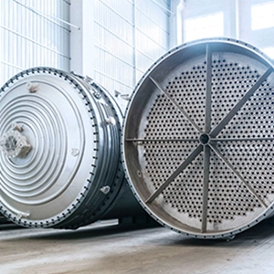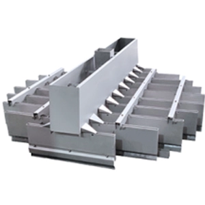
Extraction tower internals control how two liquid phases contact each other, exchange solutes, and move through a column. Distributor geometry establishes the initial phase distribution, packing influences subsequent flow and droplet behavior, and pulsation changes the hydrodynamic conditions governing mass transfer and hydraulic capacity. These components form the core of an effective torre de extracción design.
The design challenge is to achieve the required separation without excessive backmixing, unstable countercurrent flow, flooding, or poor phase disengagement. These constraints must be evaluated together because improving one performance measure can worsen another.
How Extraction Tower Internals Affect Separation Performance
Liquid-liquid extraction transfers a target component between two immiscible liquid phases. The dispersed phase forms droplets within the continuous phase, creating an interface for solute transfer.
| Internal component | Primary function | Main design variables |
|---|---|---|
| Distributor | Introduces and distributes a liquid phase | Hole geometry, discharge velocity, wetting, and cross-sectional coverage |
| Packing | Influences flow paths and droplet interactions | Geometry, material, wetting, channeling, and hydraulic resistance |
| Pulsation system | Introduces oscillatory liquid movement | Frequency, amplitude, holdup, mass transfer, and flooding limits |
The distributor establishes the initial discharge conditions, packing influences downstream phase contact, and pulsation can intensify droplet breakup and interface renewal. The design must balance these effects against hydraulic capacity and the ability of the outlet phases to separate.
Distributor Design for Liquid-Liquid Extraction
Dispersed-Phase Introduction and Wetting Behavior
The dispersed phase must leave distributor openings cleanly to establish the intended droplet formation pattern. The supplied reference identifies two approaches to achieving this behavior.
- Use a distributor material that is preferentially wetted by the continuous phase.
- Use nozzles that project beyond the distributor surface so the dispersed phase issues from the nozzle rather than spreading along the surface.
Some perforated-plate designs retain the burr created during hole punching to influence discharge behavior. This is a specific design technique, not a universal requirement.
Both phases also need appropriate distribution. Poor continuous-phase distribution can create preferential flow paths and increase backmixing, while poor dispersed-phase distribution can produce uneven droplet loading. The distributor arrangement must therefore be compatible with the flow characteristics of the downstream contacting section and the selected column internals.
Hole Diameter, Velocity, and Weber Number
For a distributor with identical openings, the required hole count can be estimated from the dispersed-phase flow rate and selected hole velocity.
[
N_{\mathrm{holes}}=\frac{Q_d}{A_oV_o}
]
Dónde:
- (N_{\mathrm{holes}}) is the number of holes.
- (Q_d) is the total volumetric flow rate of the dispersed phase.
- (A_o) is the cross-sectional area of one hole.
- (V_o) is the average velocity through each hole.
The calculated hole count is a preliminary sizing value. The final count must be a manufacturable integer, after which the actual hole velocity should be recalculated using the selected geometry and operating flow rate.
The Weber number relates inertial forces to interfacial tension. Using hole diameter as the characteristic length,
[
We=\frac{\rho_pV_o^2d}{\sigma}
]
Where (\rho_p) is the dispersed-phase density, (V_o) is hole velocity, (d) is hole diameter, and (\sigma) is interfacial tension.
The supplied reference gives the following velocity relationship for a Weber number of 12.
[
V_{o,\max}=\sqrt{\frac{12\sigma}{d\rho_p}}
]
The source identifies a Weber number of approximately 2 as a minimum guideline for achieving jetting through all holes and 8–12 as a common design range for a new design. These values are source-specific engineering guidelines, not universal limits for every liquid system.
The relationship also shows how fluid properties affect distributor sizing. At a fixed hole diameter and target Weber number, higher interfacial tension requires a higher characteristic velocity, while higher dispersed-phase density reduces the corresponding velocity. The selected operating point must still be checked against actual discharge behavior and hydraulic constraints.
Perforated Plate Layout and Flow Distribution
The supplied reference provides the following typical ranges for sieve-plate distributors.
| Parámetro | Reference range |
|---|---|
| Hole diameter | 3.2–6.4 mm |
| Hole spacing | 12.7–18.1 mm |
| Total hole area divided by column cross-sectional area | 15%–25% |
| Average linear velocity through holes | 0.152–0.305 m/s |
These values provide preliminary guidance rather than final equipment specifications. The source also notes that hole size may have relatively little effect on extraction rate in many systems, although smaller holes can improve performance in systems with high interfacial tension.
Total opening area alone does not establish uniform distribution. Hole count, spacing, layout, wetting behavior, and discharge velocity must be evaluated together to determine whether the distributor provides adequate cross-sectional coverage.
Distributor Verification
A distributor can meet its nominal flow requirement while still producing uneven discharge. Potential causes include unsuitable wetting characteristics, inconsistent hole flow, partial blockage, inadequate coverage, and changes in fluid properties.
Verification should connect the distributor design to downstream performance. If distribution is uneven, inspect the opening layout and discharge conditions before changing pulse settings. Otherwise, stronger pulsation may intensify droplet breakup without correcting the underlying maldistribution.
Packing Selection for Mass Transfer and Hydraulic Stability
Random Packing vs. Fixed Packing
Packing influences droplet movement, flow paths, and phase contact throughout the column. Its suitability depends on geometry, material, fluid properties, and operating conditions.
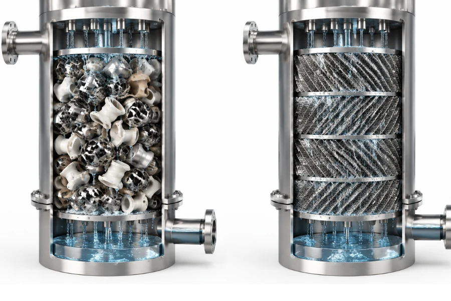
The supplied reference notes that random packing can reorient under pulsation, potentially causing channeling. Fixed packing made from corrugated expanded-metal plates is presented as an alternative for pulsed columns because it maintains a defined arrangement.
| Selection factor | Random packing | Fixed packing |
|---|---|---|
| Arrangement | Individual elements occupy a packed bed | Elements maintain a defined geometry |
| Potential issue under pulsation | Reorientation may contribute to channeling | Fixed geometry reduces the risk of packing reorientation |
| Main design concern | Element arrangement and flow distribution | Passage geometry, structural stability, and phase distribution |
This comparison does not establish a universal performance ranking. The choice depends on the extraction duty, packing geometry, fluid properties, and whether the column operates with pulsation. For applications using embalaje estructurado, the actual geometry and phase-wetting behavior must still be assessed for the intended liquid-liquid system.
Wetting and Interfacial Area
Packing material affects how the liquid phases interact with internal surfaces. The supplied reference reports that polyethylene packing, which is not wetted by aqueous solutions, provided higher flow capacities and mass-transfer rates than wetted ceramic packing in the systems discussed by the source.
This result should not be generalized to every polyethylene and ceramic packing combination. It demonstrates that material wettability can influence performance and must be evaluated for the actual phase pair.
The relevant design question is which phase preferentially wets the packing and how that behavior affects liquid distribution, droplet formation, and phase movement. Material compatibility and fouling tendency also matter because deposits or degradation can alter effective flow passages during operation.
Backmixing, Holdup, and Flooding
Packed and trayed extraction columns can improve mass-transfer performance by limiting backmixing. However, the supplied reference identifies a relatively narrow application range for these designs compared with mechanically agitated extractors.
The reference describes typical applications involving:
- Liquid viscosities below approximately 5 cP.
- Low to moderate interfacial tensions, typically 3–20 dyn/cm, equivalent to 0.003–0.02 N/m.
- Separation duties requiring no more than approximately three to five equilibrium stages.
These values are preliminary selection guidance from the source, not universal operating limits. Actual suitability depends on the fluid system, column geometry, throughput, and required separation.
Dispersed-phase holdup is the fraction of column volume occupied by the dispersed phase at a given time. Higher holdup may accompany increased interfacial area, but it is not a direct measure of extraction efficiency. Excessive accumulation can reduce hydraulic margin and contribute to flooding.
Flooding occurs when the imposed phase flow rates can no longer be sustained in stable countercurrent operation. Dispersed-phase accumulation can obstruct movement of the opposing phase, destabilize the flow pattern, and limit throughput.
Packing selection should therefore consider the separation duty, phase properties, required throughput, backmixing, and hydraulic capacity together.
Pulsation Design and Operating Parameters
Pulse Frequency, Amplitude, and Pulsed Volume
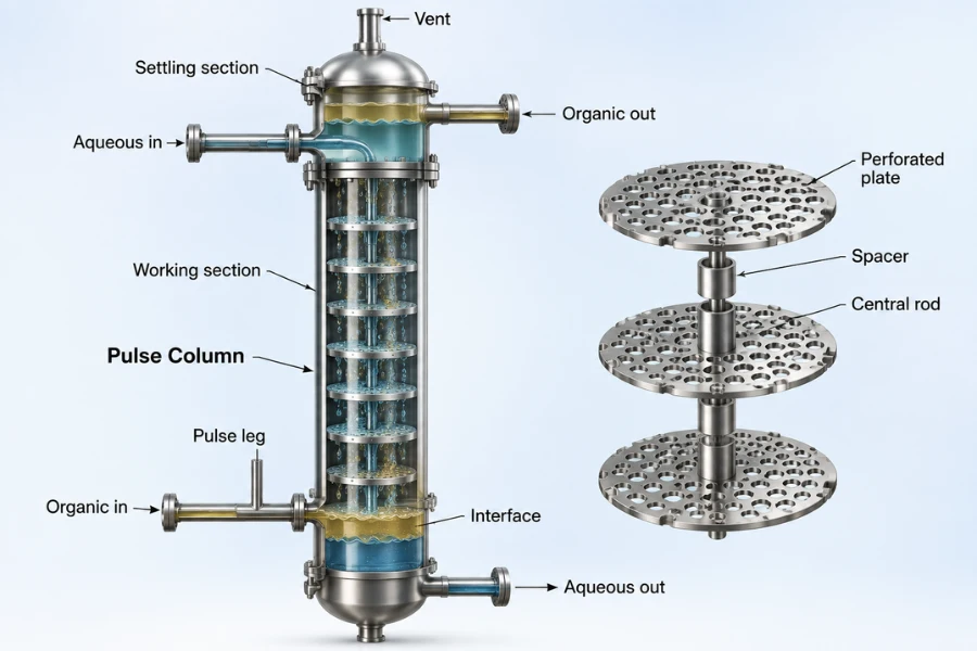
Pulsation introduces oscillatory liquid movement to intensify phase contact. The supplied reference defines three parameters.
- Frequency is the number of pulse cycles per unit time.
- Amplitude is the distance between the extreme positions of the liquid in the column, not the mechanical stroke of the pulse generator.
- Pulsed volume flow rate is the volume of liquid displaced per unit time under the specified pulse action.
The relationship is
[
Q_{\mathrm{pulse}}=AfS_c
]
Where (Q_{\mathrm{pulse}}) is pulsed volume flow rate, (A) is liquid displacement amplitude, (f) is frequency, and (S_c) is the column cross-sectional area.
This quantity describes oscillatory movement, not the net process flow rate through the column. Amplitude and frequency are also not interchangeable. Different combinations can produce the same calculated pulsed volume flow rate while imposing different displacement distances and cycle frequencies.
How Pulsation Changes Mass Transfer
The supplied reference identifies several effects of pulsation in packed extraction columns. It can reduce dispersed-phase droplet size, increase holdup, and increase interfacial area. The source also reports a considerable reduction in HETv for the systems discussed.
HETv is retained as the original source term because the supplied excerpt does not establish its full definition. It should not be silently replaced with HETP or another mass-transfer height metric without checking the original terminology.
These effects do not guarantee a proportional improvement in overall extraction performance. Smaller droplets can increase interfacial area, but the net result also depends on solute diffusion, residence time, phase properties, axial mixing, and downstream phase disengagement.
Pulsation Trade-Offs and Operating Limits
Pulsation can intensify mass transfer while reducing maximum throughput in some systems. The supplied reference specifically notes an increased tendency toward emulsification and a reduction in maximum throughput in pulsed packed columns.
| Performance objective | Potential benefit | Limitation to check |
|---|---|---|
| Increase interfacial area | Smaller droplets can provide more contact area | Excessive dispersion may complicate phase separation |
| Improve mass transfer | Stronger interface renewal | Axial mixing may reduce the effective driving force |
| Increase holdup | More dispersed liquid may remain in the contacting zone | Excessive accumulation can reduce hydraulic margin |
| Maintain throughput | Suitable pulse conditions may improve contacting | Higher intensity can bring the column closer to flooding |
A pilot-scale study of an L-shaped pulsed packed extraction column investigated specific organic-water systems, including butyl acetate-water and toluene-water. Under the tested conditions, pressure drop depended on phase flow rates and pulsation intensity, while increased pulsation intensity and dispersed-phase flow reduced maximum throughput.
These findings support evaluating mass transfer and hydraulic capacity together. They should not be generalized into a universal relationship because the outcome depends on the fluid system, column configuration, and operating regime.
Pulsed Packed and Sieve-Plate Columns
In a pulsed packed column, packing geometry influences droplet movement and can introduce preferential flow paths. The risk of random packing reorientation is one reason the supplied reference discusses fixed corrugated expanded-metal packing.
In a pulsed sieve-plate column, horizontal perforated plates span the column cross-section. The standard arrangement described in the reference does not use downcomers of the type found in conventional sieve-tray distillation columns.
The choice between these configurations depends on the separation duty, fluid properties, operating range, hydraulic capacity, and maintenance requirements. Performance data from one configuration should not be transferred to another without validation.
For multisection systems, the supplied reference also describes the potential to use one pulse generator for several short columns connected in series. Reduced static head may lower power requirements, but the arrangement must be assessed against the actual system layout and operating conditions.
Integrated Design and Scale-Up
A practical design sequence connects the process requirements to the selection and verification of the internal components.
- Define the separation duty. Establish the target component, required recovery or purity, expected feed variability, and solvent requirements.
- Characterize both phases. Determine density, viscosity, interfacial tension, wetting behavior, and material compatibility.
- Select the dispersed phase. Consider phase flow rates, fluid properties, and the intended countercurrent arrangement.
- Size the distributor. Estimate hole count and velocity, then check wetting, opening layout, and cross-sectional coverage.
- Select the packing. Evaluate geometry, material, flow distribution, fouling risk, and compatibility with pulsation.
- Assess pulsation. Determine whether additional contacting intensity is required and evaluate candidate amplitude and frequency settings.
- Check hydraulic limits. Relate phase flow rates and pulse settings to pressure drop, holdup, flooding, and phase disengagement.
- Validate the design. Use calculations and pilot testing to establish a stable operating window before commercial scale-up.
The sequence also provides a basis for troubleshooting. If stronger pulsation increases droplet breakup but worsens outlet phase clarity, investigate whether the gain in interfacial area is offset by poorer coalescence or disengagement. If pressure drop rises alongside holdup, compare both phase flow rates and pulse settings before concluding that flooding is the cause.
Pilot Testing and Troubleshooting
Pilot testing should determine whether the selected configuration achieves the required separation across the intended operating range. The value of a test matrix lies in connecting operating conditions to measured outcomes.
| Measurement | What it helps establish |
|---|---|
| Phase properties | Whether the test represents the intended process system |
| Distributor geometry and discharge conditions | Whether the initial dispersion is consistent with the design basis |
| Packing configuration | Whether geometry and material affect flow distribution |
| Pulse frequency and amplitude | How imposed motion relates to mass transfer and hydraulic behavior |
| Pressure drop and holdup | Whether hydraulic loading is approaching a limit |
| Feed and outlet compositions | Whether the required separation is achieved |
| Outlet phase disengagement | Whether entrainment or poor coalescence limits downstream operation |
The measurements should be interpreted together.
- If pressure drop increases while holdup rises, investigate dispersed-phase accumulation and hydraulic loading.
- If smaller droplets coincide with poorer outlet clarity, assess whether stronger dispersion is making phase disengagement more difficult.
- If mass transfer remains low despite increased pulsation, examine distribution uniformity, packing flow paths, and the potential effects of axial mixing.
- If performance varies between repeated runs, check whether the internal configuration maintains a reproducible flow pattern across the tested operating range.
Scale-up should preserve validated process behavior rather than simply reproduce a geometric ratio. Changes in column diameter, internal arrangement, and operating conditions can alter phase distribution, droplet behavior, and hydraulic capacity.
Before commercial design, confirm that pilot results demonstrate repeatable separation performance with adequate hydraulic margin. A configuration that meets the separation target only near an unstable operating limit may not provide a reliable basis for continuous industrial production. DODGEN’s soluciones de tecnología de procesos can be explored in the context of process engineering and industrial scale-up requirements.
Engineering Checklist for Extraction Tower Internals
- The separation target, feed variability, and solvent requirements are defined.
- Density, viscosity, interfacial tension, and material compatibility are established.
- The dispersed phase and countercurrent arrangement are justified.
- Distributor hole count, velocity, wetting, and cross-sectional coverage have been evaluated.
- Both phases are distributed appropriately through the contacting section.
- Packing geometry and material suit the fluid properties and operating regime.
- Pulse frequency and amplitude are supported by calculations or test data.
- Pressure drop, holdup, and flooding limits are evaluated together.
- Mass-transfer performance and outlet phase disengagement are assessed together.
- Pilot results support the proposed industrial operating window.
This checklist supports design review but does not replace process-specific calculations, hydraulic assessment, or pilot testing.
Conclusión
Extraction tower design requires a balance between separation performance and hydraulic stability. Distributor sizing, packing selection, and pulsation settings should be validated against the fluid properties, required separation, and operating range.
The preferred configuration is the one that meets the separation duty while maintaining stable countercurrent flow and acceptable phase disengagement. Process-specific calculations and pilot testing should establish whether that performance can be sustained at industrial scale.
For industrial separation projects, DODGEN supports process engineering, separation-system optimization, and pilot-to-commercial scale-up planning.