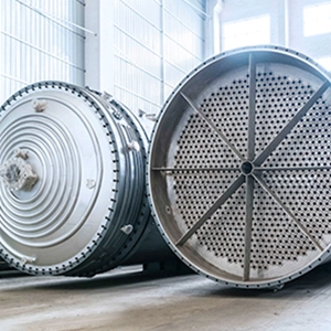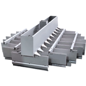
Column internals installation quality affects liquid distribution, vapor flow, separation efficiency, and operating capacity. Blocked distributor outlets, leaking collector joints, and restricted packing support openings can cause maldistribution, increase pressure drop, and contribute to premature flooding.
Reliable installation requires both mechanical verification and functional testing. This guide explains how to prepare, install, inspect, and maintain liquid distributors, liquid collectors, and packing support plates used in industrial separation equipment, with practical methods for identifying defects and verifying corrective work.
Why Column Internals Installation Quality Matters
Packed columns depend on coordinated gas-liquid flow. Distributors spread liquid across the packing, collectors gather and redirect liquid between sections, and support plates carry the packing while preserving the required flow passages.
A defect in one component can affect other sections of the column. Liquid escaping from a collector may bypass the intended redistributor, while insufficient support plate open area can restrict vapor flow even when the packing itself is clean.
The main failure mechanisms include:
- Liquid maldistribution. Uneven discharge or unintended leakage creates poorly wetted regions and localized liquid loading.
- Restricted vapor flow. Insufficient effective open area increases local gas velocity and can contribute to premature flooding.
- Mechanical damage. Incorrect support assembly, loose fasteners, or crushed packing changes the intended internal geometry.
- Reduced separation performance. Maldistribution and hydraulic restrictions can reduce mass transfer efficiency and operating capacity.
Kister’s installation guidance emphasizes that mechanical inspection alone may miss defects affecting capacity, energy consumption, and product purity. Perry’s Handbook of Chemical Engineering provides the corresponding design principles for liquid distribution and packing support.
Preinstallation Planning and Internal Assembly
Verify Drawings, Materials, and Dimensions
Review the approved internal drawings, component list, and equipment specifications before introducing components into the column. For replacement work, also verify existing support elevations, attachment locations, and relevant vessel dimensions.
Check the following items:
- Column internal diameter, roundness, and specified dimensions.
- Support ring elevations, wall clip positions, and attachment details.
- Component identification, dimensions, and assembly orientation.
- Manway access and restrictions on introducing large components.
- Materials, fasteners, gaskets, and joining methods.
- Component quantities against the supplied parts list.
Dimensional discrepancies can prevent segmented internals from fitting correctly. Evaluate proposed field modifications against the approved design rather than forcing components into place. Material substitutions also require verification because incompatible alloys, gaskets, or fasteners can introduce corrosion, leakage, or structural integrity problems.
Mock Up Internals Before Installation
Arrange segmented internals on the ground according to the relevant drawings before installing them inside the column. Verify segment identification, connection points, orientation, and fastening arrangements against the parts list.
A mock-up helps identify missing components, mismatched sections, and assembly errors while access remains convenient. It also establishes the installation sequence, including which components must be installed before access becomes restricted by the packing or adjacent internals.
Control Cleanliness and Installation Sequence
Welding, grinding, and cutting can leave debris that blocks distributor outlets or contaminates the packing. Complete debris-producing work before packing installation wherever the approved construction sequence permits.
If hot work is required after packing is installed, follow the approved hot-work procedure and protect combustible packing, personnel, and adjacent equipment.
A typical packed-section sequence is to verify the supporting structure, install the packing support, load the packing using the specified method, fit any required retainer, and install the distributor and associated internals according to the approved drawings. The actual sequence depends on the column configuration and component design.
Liquid Distributor Installation and Inspection
Liquid distributors spread incoming liquid across the top of a packed bed. Their geometry, elevation, feed arrangement, and outlet condition determine whether liquid reaches the intended distribution points.
Select the Appropriate Distributor Type
Perry’s Handbook of Chemical Engineering, Section 14 in the supplied seventh- and eighth-edition excerpts, describes trough, orifice-riser, and perforated-pipe distributors. Their suitability depends on liquid loading, available liquid head, gas-flow requirements, and process-fluid characteristics.
| Distributor type | Design characteristics | Main limitations |
|---|---|---|
| Trough distributor | Can provide good distribution over varying gas and liquid rates; some designs accommodate limited solids deposition | Uneven trough elevation, damaged weirs, or blocked outlets can alter discharge |
| Orifice-riser distributor | Uses multiple discharge points and can limit liquid-gas contact within the distributor | Requires adequate liquid head, and gas risers must accommodate the expected vapor flow |
| Perforated-pipe distributor | Uses a feed sump and branching pipes to distribute liquid through perforations | Small openings are susceptible to plugging, and inadequate supply can starve outlets near pipe ends |
Distributor selection must match the intended operating range. A design that distributes adequately at high liquid loading may perform poorly at low rates if its hydraulic characteristics do not support the required turndown.
Check Levelness, Orientation, and Liquid Feed
Uneven distributor elevation can create differences in liquid head and discharge rate, leaving some regions of the packing underwetted. This is particularly important in large-diameter columns operating at low liquid rates.
Perry’s provides an illustrative levelness tolerance of approximately 6 mm for a 3 m diameter column under the relevant distribution conditions. This is a design example, not a universal acceptance tolerance. Actual requirements depend on distributor geometry, liquid loading, packing sensitivity, and approved equipment specifications.
Inspect the distributor for:
- Correct orientation of troughs, pans, and pipes.
- Alignment and levelness against the approved drawings.
- Obstructed weirs, drip tubes, or perforations.
- Correct feed connection and liquid entry location.
- Required distribution points near the column wall.
- Missing fasteners, damaged gaskets, and unintended leakage paths.
For perforated-pipe distributors, check whether the lateral pipes supply sufficient liquid to their end outlets. Incorrect pipe sizing, perforation arrangements, or liquid head can cause uneven discharge even when the feed connection is correctly installed.
Conduct Distributor Flow Tests
A distributor flow test can reveal defects that visual inspection alone may miss. Where compatible with the equipment and process requirements, use clean water to assess the discharge pattern before closing the column.
Follow an approved test procedure and record the test flow rate, relevant liquid head, test configuration, and observed discharge. Evaluate the results at three levels.
1. Outlet function
Confirm that intended outlets discharge and that no openings are blocked, damaged, or leaking through unintended paths. Investigate missing bolts or incorrectly assembled joints that allow liquid to bypass the designed outlets.
2. Distribution coverage
Check whether discharge points cover the intended column cross-section, including near-wall locations where the design requires them. A distributor can have functioning outlets but still leave parts of the packing insufficiently irrigated if the distribution-point arrangement is incomplete or incorrectly positioned.
3. Design compliance
Compare the observed distribution with the applicable design acceptance criteria. These may address outlet performance, distribution-point coverage, or flow variation, depending on the distributor design and approved test procedure. Do not apply a universal flow-deviation percentage unless the equipment specification explicitly requires it.
Kister describes distributor failures involving inconsistently oriented openings and missing bolts that allowed liquid to escape through unintended openings. These cases show why flow testing can reveal assembly defects that a mechanical checklist misses.
A water test does not establish performance under every process condition. Differences in viscosity, surface tension, temperature, liquid loading, and fouling behavior can change actual distribution. Test results must therefore be interpreted within the tested conditions and the intended operating range.
Maintain and Troubleshoot Distributors
Maintenance should address the verified failure mechanism rather than default to cleaning or replacement.
| Defect | Likely effect | Corrective approach |
|---|---|---|
| Blocked perforations or outlets | Reduced discharge at affected points | Remove deposits using a material-compatible method and investigate recurring fouling |
| Corroded or eroded weirs and outlets | Altered discharge geometry | Assess material loss and replace components when dimensional or functional integrity is compromised |
| Leakage through joints or missing fasteners | Uncontrolled liquid bypass | Restore the specified joint configuration and repeat the applicable flow test |
| Incorrect distributor elevation | Uneven liquid head and discharge | Recheck alignment against the approved design |
| Poor distribution across the operating range | Inadequate hydraulic performance at certain loads | Review liquid head, feed conditions, and distributor suitability |
When separation efficiency declines at low liquid loading, maldistribution is one possible cause. Check distributor performance alongside feed composition, packing condition, and other operating changes.
If the distributor is correctly installed but cannot meet the required distribution range, cleaning alone may not resolve the problem. An engineering review may be needed to assess the feed arrangement or distributor design.
Liquid Collector Installation and Maintenance
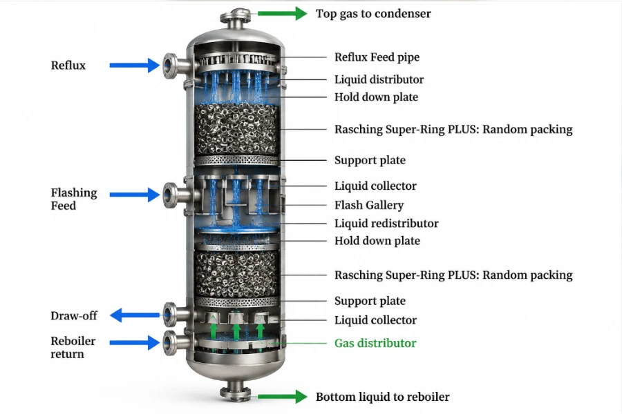
Liquid collectors gather descending liquid from an upper packed section and route it to a redistributor, draw-off line, pump-around circuit, or other designated destination. Some designs also provide a controlled passage for rising vapor.
The required liquid path depends on the collector’s process duty. A collector may remove all the collected liquid from the column, withdraw only part while allowing the remainder to continue downward, or collect and mix liquid streams before routing them to the next section. These duties affect outlet arrangements, overflow paths, and the design of downstream distribution equipment.
Inspection must therefore establish whether the collector performs its intended collection, withdrawal, drainage, and redistribution functions while preserving the required gas-flow path.
Verify Collector Position and Connections
Confirm the collector segment arrangement, support points, connection details, and orientation against the approved drawings. After assembly, inspect panel interfaces and connections to the column wall or support structure.
Pay particular attention to:
- Correct panel identification and assembly.
- Specified fastening and gasket arrangements.
- Perimeter and segment joints that could permit liquid bypass.
- Drainage openings and designated liquid outlets.
- Chimneys, risers, and other gas passages where present.
- Thermal expansion provisions specified in the design.
Do not add or eliminate expansion gaps without engineering approval. Either change can compromise sealing or introduce unwanted mechanical stress.
Distinguish Collection, Drainage, and Redistribution Problems
Collector defects can affect different parts of the liquid path.
Leakage allows liquid to bypass the intended collection and redistribution route. The lower packing bed may receive liquid through uncontrolled paths, creating localized loading.
Restricted drainage prevents collected liquid from leaving at the intended rate. Liquid may accumulate even if the collector’s perimeter seals remain intact.
Obstructed vapor passages restrict gas flow through chimney-type collectors. This can create a hydraulic limitation independently of liquid leakage.
These mechanisms require different corrective actions. Inspection should identify the affected flow path rather than treating all collector problems as sealing failures.
Test Collector Integrity Within Design Limits
Kister identifies water testing as a useful method for checking collector trays intended to resist or prevent leakage. Where permitted, the test can reveal leakage paths that visual inspection alone may miss.
The approved procedure must define the test level, duration, and acceptance criteria. Do not completely fill a collector with water unless its design permits the resulting load.
If a liquid test is not permitted or cannot reproduce the relevant condition, use an alternative inspection or verification method approved for the equipment. After repair, confirm that the collector routes liquid correctly and that sealing work has not restricted gas or liquid passages.
Packing Support Plate Installation and Inspection
Packing support plates and grids carry the packed-bed load while allowing gas and liquid to pass through the column. Their structural capacity and effective open area are separate design requirements.
A mechanically sound support may still restrict vapor flow if its effective open area is insufficient. Conversely, large openings do not compensate for inadequate load capacity or incorrect support geometry.
Verify Support Geometry and Structural Fit
Check column dimensions, support elevations, bearing surfaces, and attachment points before installing the support plate. Segments must fit the designated rings, beams, or wall clips and be secured according to the approved design.
Random packing and structured packings can require different support configurations, so the installation checks should reflect the actual arrangement.
For random packing supported on multiple beams, the packing bed surface can often be leveled through the packing installation process. The support ring itself may not be the controlling reference for the final bed surface in every such design. However, this does not remove the need to verify support geometry and bearing conditions against the drawings.
For structured packing installed on a support grid carried by a support ring, ring elevation and levelness can directly affect the grid and the packing bed above it. These requirements should follow the packing supplier’s specifications and approved equipment drawings. Do not transfer a tolerance from one support arrangement to another.
Inspect for:
- Correct bearing contact between support components and their intended surfaces.
- Fasteners and clamps installed according to the drawings.
- Support elevations and attachment geometry within specified tolerances.
- Segment joints that do not create unintended openings.
- Completed structural work before packing is exposed to construction debris or hot-work hazards.
Support ring elevation, support plate levelness, and packing bed surface levelness are distinct measurements. Verify each against the applicable design requirement.
Verify Packing Retainers and Hold-Down Devices
Some packed beds require retainers or hold-down devices to prevent packing movement under the expected operating conditions. Their design and installation depend on the packing type, column configuration, and specified operating loads.
Verify that the required devices are present, correctly positioned, and secured according to the drawings. A retainer must not obstruct the intended gas or liquid flow paths, and it should not impose unintended loads on fragile packing elements.
The absence of a required retainer, incorrect fastening, or contact that deforms packing can compromise the installed arrangement. Conversely, a retainer should not be added to a design that does not call for one without engineering review.
Evaluate Effective Open Area
Perry’s Section 14 explains that support plate design affects pressure drop and the stable operating range. An inadequately open support plate can contribute to premature flooding even when the packing itself is not fouled.
Three concepts must be distinguished.
- Geometric open area is the area provided by the support plate openings before accounting for obstruction.
- Effective open area is the portion that remains available for flow after considering the installed configuration and obstruction by packing or other components.
- Packing void space is the open space within the packing arrangement. It is not interchangeable with the open area of the support plate.
For the relevant support design, Perry’s states that the net open area must exceed the corresponding open area of the packing to avoid premature flooding caused by the support plate. This principle must be interpreted in the context of the specific support geometry, not treated as a universal calculation formula.
When the available area for upward vapor flow is restricted, the remaining passages must carry the flow at higher local velocities. This can increase resistance and contribute to an early hydraulic limitation. Packing placement, deposits, and misplaced components can reduce effective flow area even when the nominal plate openings appear adequate.
Inspection should verify both the structural configuration and the unobstructed flow passages. Adequate open area does not, by itself, prove that the support has sufficient mechanical capacity.
Inspect Deformation, Corrosion, and Packing Damage
Inspect support plates and attachments for bending, sagging, corrosion, cracking, erosion, and loose or damaged fasteners. Deposits and retained liquid may increase structural loading, while operating disturbances can impose additional stresses.
Packing condition should be checked alongside support integrity. Kister describes a case in which workers stepped on and crushed intermediate layers of structured packing, contributing to premature flooding at approximately half the design load. The case illustrates how installation damage can change hydraulic performance even when the support structure remains in place.
Crushed random packing and deformed structured packing can alter flow resistance or create uneven passages. Replacing damaged packing without addressing a displaced or weakened support may leave the underlying cause unresolved.
Corrective work should follow an assessment of the defect’s extent. It may require removing deposits, replacing fasteners, repairing or replacing support components, restoring the specified geometry, or replacing damaged packing. Structural repairs require engineering review rather than an assumption that minor adjustments will restore the original capacity.
Prestartup Inspection and Functional Testing
Before the column is closed, the inspection team should confirm that installation is complete, identified defects have been resolved, and required functional tests meet their acceptance criteria.
The final inspection should consolidate component findings rather than repeat the detailed installation procedures.
| Inspection category | Verification requirement | Record |
|---|---|---|
| Documentation | Approved drawings, component list, and specifications are available | Document references and revisions |
| Mechanical completion | Required components are installed and secured | Findings and deviations |
| Distributor functionality | Applicable flow test meets approved criteria | Test conditions and results |
| Collector integrity | Required leakage checks are completed where permitted | Test conditions and results |
| Support structure | Geometry, attachments, and flow passages meet design requirements | Measurements and defects |
| Packing retainers | Required devices are installed and do not obstruct intended flow paths | Inspection findings |
| Cleanliness | Construction debris and foreign materials are removed | Final inspection confirmation |
| Defect closure | Required repairs and replacements are verified | Corrective action records |
| Final release | Required inspections and approvals are complete | Authorized signoff |
Use each test to verify the function it is intended to assess. A distributor flow test evaluates liquid discharge, while a collector leak test evaluates sealing under specified conditions. Neither replaces structural inspection or demonstrates performance under every operating condition.
Document unresolved deviations and obtain the required engineering disposition before final release.
Troubleshooting Column Internals Performance
Operating symptoms help direct an investigation but rarely establish a unique root cause. Diagnosis should combine process data, recent operating changes, inspection findings, and the expected behavior of the relevant internal.
Begin by reviewing operating trends, identifying the impaired process function, and selecting an inspection or test that can distinguish between plausible causes.
| Operating symptom | Potential causes | Evidence to review |
|---|---|---|
| Reduced separation efficiency with little change in pressure drop | Liquid maldistribution, packing damage, or changed process conditions | Distributor test results, available temperature profiles, packing condition, and process data |
| Rising pressure drop and reduced capacity | Restricted support openings, packing fouling, excessive liquid loading, or flooding | Pressure-drop trends, operating loads, and internal inspection findings |
| Uneven liquid distribution in a lower bed | Collector leakage or incorrect redistribution | Collector joint condition and downstream distributor performance |
| Poor separation at low liquid rates | Distributor turndown limitations, blocked outlets, or incorrect leveling | Feed conditions, distributor geometry, and flow test results |
| Repeated problems after maintenance | Incomplete repair, incorrect assembly, or unresolved process causes | Previous inspection records, repair details, and repeat-test results |
| Packing displacement or localized damage | Support instability, incorrect installation, or operating disturbances | Support structure, hold-down devices, and packing condition |
An increase in pressure drop, for example, may result from packing fouling, excessive liquid loading, restricted support passages, or flooding. Operating data and physical findings are needed to distinguish these possibilities.
If multiple defects are present, correcting only the most visible one may not restore performance. The investigation should continue until the evidence supports the selected corrective action.
Maintenance Planning and Post-Repair Verification
Maintenance intervals should reflect process service, equipment design, operating history, and the consequences of failure. A single calendar-based interval is unlikely to suit every packed column.
Fouling or solids-bearing services may require closer attention to distributor openings and packing condition. Corrosive services may require more detailed examination of wetted surfaces, joints, and fasteners. Repeated defects should trigger a review of the underlying cause rather than an automatic increase in cleaning frequency.
Maintain records of defect locations, operating symptoms, inspection findings, repairs, test results, and outstanding deviations. These records help identify recurring problems and determine whether maintenance methods, process conditions, or equipment design need further review.
After corrective work, verify the function affected by the repair. Depending on the work performed, this may involve checking alignment, confirming clear passages, repeating an applicable distributor flow test, or completing a permitted collector leak test.
After startup, compare pressure drop, separation performance, throughput, and other relevant process indicators with historical or design-based reference data. Interpret changes alongside feed composition and operating load to determine whether the repair restored the intended performance.
Conclusion
Reliable column internals performance depends on the combined integrity of liquid distributors, liquid collectors, and packing support plates. Correct installation establishes the intended geometry, functional testing checks critical hydraulic behavior, and evidence-based maintenance helps preserve operating performance.
The essential task is to verify that the installed configuration matches the approved design, that identified defects have been corrected, and that subsequent operating data support stable performance. For DODGEN‘s industrial process engineering and integration work, this approach connects internal component condition with separation requirements, operating constraints, and production reliability.