Reactor performance depends on how effectively reaction heat is supplied, removed, and recovered. In continuous chemical manufacturing, inadequate thermal management can create temperature gradients, reduce reaction selectivity, accelerate catalyst deactivation, and increase utility consumption.
Integrated reactor and heat exchanger design addresses these challenges by coordinating reaction and heat transfer at the equipment and process levels. Configurations range from jacketed reactors and external circulation loops to feed-effluent heat exchangers (FEHEs) and compact heat exchanger reactors.
However, maximizing heat recovery does not necessarily produce the most stable or economical process. Greater thermal integration can strengthen interactions between reactor inlet and outlet temperatures, affecting reaction kinetics, control response, and operating flexibility.
The design objective is to recover useful energy while maintaining adequate heat transfer capacity, reaction temperature control, and long-term process stability.
Why Integrate Reactor and Heat Exchanger Systems?
Thermal Management Challenges in Chemical Reactors
Exothermic reactions release heat that must be removed to maintain the required operating temperature. Endothermic reactions consume heat and require continuous energy input to sustain the desired reaction rate and conversion.
In exothermic systems, insufficient heat removal can cause temperature increases that accelerate reaction kinetics. If heat generation continues to exceed heat removal, thermal accumulation can develop into a runaway condition.
Temperature distribution also affects catalytic performance. Localized hot spots in packed-bed reactors can accelerate catalyst deactivation, promote unwanted side reactions, and create uneven conversion across the catalyst bed.
These challenges become more significant during scale-up. Reactor volume can increase faster than available heat transfer area, making the relationship between reaction heat generation and cooling capacity a critical design constraint.
Engineering Benefits of Thermal Integration
Integrating reaction and heat exchange functions can provide several process advantages.
- Temperature regulation: Distributed heat transfer surfaces can reduce local temperature gradients and improve thermal control.
- Energy recovery: Hot reactor effluent can preheat incoming feed or supply heat to other process operations.
- Utility reduction: Recovered process heat can reduce external heating demand, while appropriate heat removal can reduce cooling requirements.
- Equipment intensification: Combining reaction and heat transfer functions can reduce equipment volume in applications suited to compact designs.
- Process integration: Coordinating reactor operation with downstream heat recovery can improve overall energy utilization.
These benefits depend on reaction kinetics, fluid properties, heat transfer requirements, and operating conditions. A configuration that improves thermal efficiency may still be unsuitable if it creates excessive pressure drop, fouling, or control limitations.
Fundamental Heat Transfer Principles in Reactor Design
Heat Transfer Rate and Overall Heat Transfer Coefficient
The basic relationship for heat transfer across a reactor wall or exchanger surface is:
[Q=UA\Delta T]
장소:
- (Q) is the heat transfer rate.
- (U) is the overall heat transfer coefficient.
- (A) is the effective heat transfer area.
- (\Delta T) is the temperature difference driving heat transfer.
For a heat exchanger in which the temperature difference changes along the flow path, the design equation becomes:
[Q=UA\Delta T_{lm}]
The logarithmic mean temperature difference is:
[\Delta T_{lm}=\frac{\Delta T_1-\Delta T_2} {\ln(\Delta T_1/\Delta T_2)}]
Here, (\Delta T_1) and (\Delta T_2) represent the temperature differences at the two exchanger ends. Multipass and crossflow arrangements may require a correction factor based on their actual flow configuration.
The overall heat transfer coefficient reflects the combined thermal resistance of both fluid films, the separating wall, and any fouling layers. For a simplified plane-wall representation:
[\frac{1}{U}=
\frac{1}{h_h}
+R_{f,h}
+\frac{\delta_w}{k_w}
+R_{f,c}
+\frac{1}{h_c}]
Where (h_h) and (h_c) are the hot- and cold-side heat transfer coefficients, (R_f) represents fouling resistance, and (\delta_w/k_w) represents wall conduction resistance.
This relationship identifies the main opportunities for improving thermal performance.
- Increasing fluid velocity may improve convective heat transfer but also increases pressure drop.
- Increasing wall conductivity reduces conduction resistance.
- Increasing heat transfer area raises thermal capacity but may increase equipment size and cost.
- Fouling increases thermal resistance and can reduce performance over time.
The design must therefore optimize the combined thermal and hydraulic performance rather than maximize surface area independently.
Heat Exchanger Effectiveness and NTU
Heat exchanger effectiveness measures actual heat transfer relative to the maximum theoretically available under the specified inlet conditions.
[\varepsilon=\frac{Q_{\mathrm{actual}}}{Q_{\mathrm{max}}}]
The maximum possible heat transfer is:
[Q_{\mathrm{max}}=
C_{\min}(T_{h,in}-T_{c,in})]
Where (C_{\min}) is the smaller heat capacity flow rate of the two streams.
The number of transfer units is:
[NTU=\frac{UA}{C_{\min}}]
Effectiveness depends on NTU, the heat capacity rate ratio, and exchanger flow arrangement. Countercurrent, cocurrent, and crossflow exchangers therefore require different effectiveness-NTU relationships.
For FEHE design, these parameters help estimate recoverable heat under specified flow and temperature conditions. However, high effectiveness alone does not establish an optimal process configuration. Pressure drop, control authority, fouling, and minimum temperature approach must also be evaluated.
Reactor Energy Balance and Thermal Stability
A simplified dynamic energy balance for a constant-volume, perfectly mixed liquid-phase CSTR is:
UA(T-T_j)]
장소:
- (\rho) is the reacting fluid density.
- (V) is reactor volume.
- (C_p) is fluid heat capacity.
- (F) is volumetric feed flow rate.
- (T_f) is feed temperature.
- (T) is reactor temperature.
- (\Delta H_r) is reaction enthalpy per unit amount reacted.
- (r) is reaction rate per unit reactor volume.
- (T_j) is the effective jacket temperature.
For an exothermic reaction, (\Delta H_r) is negative, making the reaction heat generation term positive.
This model assumes constant physical properties, constant volumetric flow, and ideal mixing. Systems involving multiple phases, variable properties, evaporation, or complex reaction networks require additional energy balance terms.
At steady state, the accumulation term becomes zero. Reaction heat generation must then balance feed and product enthalpy changes, heat removal, and other thermal contributions.
For exothermic reactions, thermal stability depends on the relationship between heat generation and heat removal. Because reaction rates are temperature-dependent, a temperature increase may accelerate heat generation while the cooling system approaches its capacity limit.
Integrated Reactor and Heat Exchanger Configurations
Equipment selection depends on reaction heat load, fluid properties, catalyst requirements, operating pressure, available space, and maintenance conditions.
Jacketed Reactors
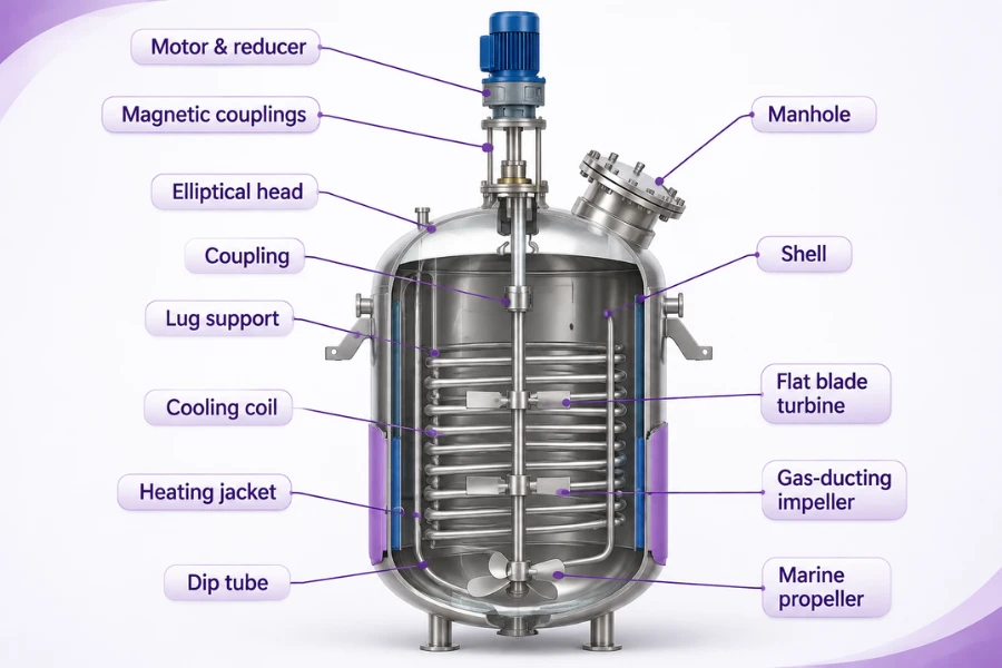
A jacketed reactor uses an external chamber surrounding the vessel to circulate a heating or cooling medium. Heat passes through the reactor wall without direct contact between the utility fluid and the reacting material.
This arrangement is suitable for many stirred-tank applications where external temperature regulation and equipment accessibility are important.
Key design considerations include jacket-side flow distribution, available heat transfer area, wall thermal resistance, and cooling medium circulation.
The main limitation is the available surface area relative to reactor volume. As reactor capacity increases, the jacket may no longer provide sufficient heat removal for highly exothermic reactions.
Internal Coil Heat Exchangers
Internal coils provide additional heat transfer surface by placing heating or cooling tubes inside the reactor.
Helical coils and other arrangements can increase thermal capacity without substantially enlarging the reactor shell. They are particularly useful when external jacket area is insufficient.
However, internal coils occupy working volume and alter the flow field. Their position and geometry can affect mixing, circulation, local temperature distribution, and catalyst or particle movement.
Coils also introduce additional cleaning and inspection requirements. The design must balance increased heat transfer area against the effect of internal structures on reactor hydrodynamics.
External Heat Transfer Circuits
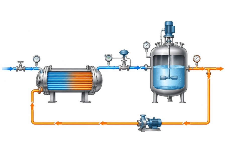
An external heat transfer circuit withdraws process material from the reactor, passes it through a separate heat exchanger, and returns the conditioned stream.
The system typically includes a circulation pump, exchanger, connecting piping, and temperature control instrumentation.
Its main advantage is that exchanger sizing can be adjusted relatively independently of the reactor vessel. It also avoids placing additional structures inside the reaction zone.
Design considerations include circulation flow rate, pump power, exchanger duty, loop pressure drop, and the time required for the conditioned stream to return to the reactor.
The circulation rate must provide adequate heat removal without introducing unacceptable changes to mixing, residence time distribution, or material integrity.
Feed-Effluent Heat Exchangers
A feed-effluent heat exchanger transfers energy from hot reactor outlet material to colder incoming feed.
A typical arrangement follows this sequence:
- Cold reactants enter the exchanger.
- The hot reactor effluent transfers sensible heat to the feed.
- Preheated reactants enter the reactor.
- The cooled product stream proceeds to downstream processing.
- Additional heating or cooling is supplied where required.
This arrangement reduces external feed heating demand and can lower the cooling duty required downstream.
However, FEHE integration also couples reactor outlet temperature to feed inlet temperature. In strongly temperature-dependent reactions, this interaction can affect reaction rate, heat generation, and process stability.
FEHE design must therefore consider dynamic behavior as well as steady-state heat recovery.
Compact Heat Exchanger Reactors and PCHE
A heat exchanger reactor combines reaction and heat transfer within an integrated equipment structure. Instead of using a conventional vessel with an external jacket, the reaction takes place within a heat transfer device.
Microchannel structures and other compact configurations can provide high surface-area-to-volume ratios and short heat transfer distances.
Printed circuit heat exchangers (PCHEs) use etched flow channels within bonded metal plates. Their compact structure makes them relevant to applications requiring high heat transfer density and pressure-resistant construction.
However, compact flow passages introduce specific design constraints.
- Small channels may be sensitive to particulate accumulation and fouling.
- Pressure drop must be evaluated alongside heat transfer performance.
- Material selection must reflect reaction chemistry, temperature, and pressure.
- Flow maldistribution can produce uneven residence time and temperature profiles.
- Inspection, cleaning, and manufacturing requirements can limit equipment suitability.
The distinction between an intensified heat transfer reactor and a true HEX reactor is important. The former improves heat transfer within a conventional reactor configuration, while the latter integrates the reaction space into the heat exchanger structure.
For continuous operation, flow distribution and residence time distribution must be evaluated alongside thermal performance. Uneven flow can produce different local reaction times and temperatures, affecting conversion and selectivity even when average outlet conditions appear acceptable.
For processes requiring compact reaction structures, DODGEN micro reactor technology is a relevant equipment category to evaluate alongside the required reaction and heat transfer conditions.
Selecting the Appropriate Configuration
| 구성 | Suitable conditions | Main limitations |
|---|---|---|
| Jacketed reactor | Stirred tanks with moderate thermal duty | Limited external heat transfer area |
| Internal coil | Additional internal surface area is required | Mixing interference and cleaning |
| External circuit | Independent exchanger sizing is important | Pumping demand and circulation response |
| FEHE | Continuous processes with recoverable hot effluent | Thermal feedback and inlet temperature control |
| HEX reactor or PCHE | Compatible continuous processes requiring compact heat transfer | Channel fouling, pressure drop, and flow distribution |
A practical selection sequence should begin with reaction heat generation or consumption, followed by fluid properties, catalyst requirements, temperature profile, hydraulic constraints, and maintenance access.
For example, high-viscosity materials or particle-containing streams may favor larger, more accessible flow passages over narrow microchannels. Clean continuous catalytic processes with high thermal demand may be more suitable for intensified heat transfer structures.
Temperature Control in Exothermic and Endothermic Reactors
Heat Removal in Exothermic Reactions
The cooling duty of an exothermic reactor depends on reaction rate, reaction enthalpy, feed composition, operating temperature, and the thermal capacity of the reacting system.
Jackets and internal coils are commonly considered for direct vessel cooling. External circulation circuits provide additional cooling capacity when internal surface area is insufficient, while staged reactors can use interstage cooling to control temperature between reaction zones.
The location of heat removal is as important as total cooling capacity. A packed-bed reactor with localized heat generation may require distributed or interstage cooling rather than a single external cooling surface.
Heat Supply in Endothermic Reactions
Endothermic reactions require continuous heat input to maintain reaction temperature and conversion.
Heating can be supplied through external circuits, internal heating surfaces, or feed preheating. The available heat source must have a sufficiently high temperature to maintain the required driving force across the exchanger.
A recovered stream may contain substantial thermal energy but remain unsuitable if its temperature is too low for the receiving process. In such cases, supplementary heating or heat upgrading may be necessary.
Feedback and Feedforward Temperature Control
Feedback control regulates reactor temperature by comparing measured temperature with a set point and adjusting heating or cooling medium flow.
A typical control arrangement includes reactor temperature sensors, a controller, a control valve, and the corresponding heating or cooling circuit.
Feedforward control can complement feedback by responding to measurable disturbances before they create substantial temperature deviations. Changes in feed flow or inlet temperature, for example, can be used to anticipate changes in reactor thermal demand.
Control performance depends on sensor placement, process dead time, exchanger response, valve characteristics, and reactor thermal inertia.
Normal temperature control must also remain separate from independent safety protection. High-temperature alarms, interlocks, and emergency shutdown functions should be established through an appropriate process hazard assessment.
Hot Spot Prevention and Thermal Runaway Risk
Hot spots and thermal runaway are related but distinct problems.
A hot spot is a localized region with a temperature higher than its surroundings. It commonly develops when local heat generation exceeds the rate of heat removal from that region.
Thermal runaway involves accelerating temperature increase caused by an imbalance between reaction heat generation and heat removal. Temperature-dependent reaction kinetics can reinforce thermal accumulation.
| Engineering aspect | Hot spot | Thermal runaway |
|---|---|---|
| Main characteristic | Localized temperature elevation | Accelerating temperature increase |
| Typical location | Catalyst beds and local reaction zones | Reactor-wide or localized reactive regions |
| Main contributing factors | Flow maldistribution and local heat transfer limitations | Reaction kinetics and inadequate heat removal |
| Potential consequences | Selectivity loss and catalyst damage | Severe temperature escalation and equipment damage |
| Main control approaches | Distributed cooling and flow management | Reaction load management and independent safety protection |
Hot spot management may require changes to catalyst loading, feed distribution, cooling surface placement, and reactor flow conditions.
For example, improving catalyst distribution can reduce localized reaction intensity, while multipoint temperature monitoring can reveal thermal gradients that a single outlet temperature measurement would miss.
Increasing exchanger area alone may not solve a hot spot caused by uneven catalyst activity or poor flow distribution.
Heat Recovery Strategies for Integrated Reactor Systems
Heat recovery should match available process heat with a suitable receiving stream. The relevant variables include heat capacity flow rates, inlet and outlet temperatures, minimum temperature approach, and pressure drop.
Feed Preheating Through FEHE Integration
Feed preheating is one of the most direct methods of recovering heat from reactor effluent.
The recoverable duty depends on hot and cold stream flow rates, heat capacity, inlet temperatures, exchanger effectiveness, and the minimum temperature approach.
The FEHE must also preserve sufficient control over reactor inlet temperature. A bypass can provide an additional means of regulating the final feed temperature when outlet conditions change.
Interstage Heat Recovery
Multistage reactor systems provide opportunities to remove heat between reaction stages.
In exothermic catalytic processes, interstage cooling can reduce the temperature entering the next stage and maintain more suitable reaction conditions.
Recovered heat may be transferred to another feed stream, used for steam generation, or supplied to a separate process heating requirement.
The exchanger arrangement must reflect the temperature and pressure conditions of each stage. A compact exchanger may be suitable for one process stream but impractical for another if fouling, corrosion, or hydraulic constraints are significant.
Steam Generation and Process Heat Reuse
High-temperature reactor effluent may provide useful heat for boiler feedwater preheating or steam generation.
Medium- and lower-temperature streams may be better suited to feed preheating, water heating, or other process duties.
The receiving process must have a sufficiently low temperature requirement to accept the recovered heat. Otherwise, the temperature driving force will be inadequate or additional energy will be required to upgrade the heat.
Pinch Analysis and Heat Exchanger Network Integration
Pinch analysis evaluates heat recovery opportunities across multiple hot and cold process streams rather than optimizing one exchanger independently.
Hot and cold composite curves establish energy targets and identify the temperature region where heat transfer becomes most constrained.
The minimum temperature approach, expressed as (\Delta T_{\min}), determines the minimum allowable temperature difference between matched hot and cold streams.
A smaller (\Delta T_{\min}) generally increases heat recovery potential but requires greater exchanger area and capital investment. A larger value reduces exchanger requirements but increases external heating and cooling demand.
Pinch analysis can therefore help determine whether reactor effluent heat should be used for feed preheating, another process stream, or a utility system.
The theoretical maximum energy recovery target may not produce the most economical network. Equipment count, stream matching, piping distance, pressure drop, maintenance access, and control requirements must also be considered.
Heat Quality and Exergy
The quantity of recovered heat does not fully describe its usefulness. Temperature level determines which process duties can accept that energy.
High-temperature streams may support steam generation or higher-temperature feed preheating, while low-grade heat may be more suitable for water heating or heat pump applications.
Exergy analysis evaluates the useful work potential of energy and helps identify losses associated with heat transfer across large temperature differences.
Combining pinch analysis with exergy evaluation can provide a more complete basis for selecting heat recovery opportunities. Pinch analysis establishes heat recovery targets, while exergy analysis helps assess the thermodynamic quality of the recovered energy.
Engineering Challenges and Design Trade-Offs
Heat Recovery and Process Controllability
One of the most important design considerations is the interaction between thermal efficiency and dynamic controllability.
In an FEHE-integrated exothermic reactor, an increase in outlet temperature may transfer more heat to the incoming feed. The resulting inlet temperature increase can accelerate reaction kinetics and increase heat generation.
The potential feedback mechanism is:
- Reactor outlet temperature increases.
- More heat transfers to the incoming feed.
- Reactor inlet temperature rises.
- Reaction rate and heat generation may increase.
- Reactor outlet temperature may rise further.
This does not mean that every FEHE system is unstable. The actual response depends on reaction kinetics, exchanger characteristics, reactor dynamics, and control configuration.
Dynamic studies of FEHE-reactor systems have identified instability and limit cycles under specific operating conditions. Bypass valve saturation can further restrict the controller’s ability to regulate reactor inlet temperature.
Important design measures include:
- Providing sufficient bypass capacity around the exchanger.
- Maintaining adequate control valve travel and flow range.
- Controlling reactor inlet temperature independently where necessary.
- Evaluating supplementary heating requirements.
- Using dynamic simulation to assess disturbances and operating transitions.
A bypass arrangement allows part of the incoming feed to avoid the exchanger before mixing with the preheated stream. This provides an additional control variable for adjusting reactor inlet temperature.
Dynamic evaluation should also examine heat flow inversion. During transient conditions, the temperature relationship between the two streams may change, potentially reversing heat transfer direction. Startup, low-load operation, and changes in feed conditions therefore require separate evaluation from nominal steady-state operation.
Heat Transfer Efficiency and Pressure Drop
Increasing heat transfer intensity often requires higher flow velocity, smaller channels, or enhanced turbulence.
These changes can increase pressure drop and pumping power.
Compact exchangers may provide high heat transfer area per unit volume, but their suitability depends on fluid viscosity, particulate content, channel geometry, and available pumping capacity.
The design must balance heat transfer performance against hydraulic losses, blockage risk, and long-term operating conditions.
Fouling, Corrosion, and Material Compatibility
Fouling deposits increase thermal resistance and may reduce heat transfer capacity while increasing pressure drop.
Corrosion and material degradation create additional constraints in systems involving aggressive chemicals, high temperatures, or repeated thermal cycling.
Material selection should reflect process chemistry, operating pressure, temperature, corrosion mechanisms, and mechanical loading.
Cleaning and inspection access should be considered during equipment selection. A high-performance exchanger that cannot be maintained effectively may create greater lifecycle costs than a more accessible alternative.
For polymer and high-viscosity processing, DODGEN heat exchanger solutions are a relevant product category to evaluate against the material’s rheology, thermal duty, and operating requirements.
Capital Investment and Operating Cost
Integrated systems may require additional heat transfer surfaces, pumps, valves, instrumentation, and piping.
The economic evaluation should include:
- Equipment and installation costs.
- Heating and cooling utility consumption.
- Pumping power.
- Cleaning and maintenance requirements.
- Production losses during shutdowns.
- Expected operating life.
- Flexibility under changing production conditions.
Total annualized cost can compare alternative configurations by combining annualized capital investment with operating expenses.
The best design is not necessarily the one with the highest theoretical heat recovery rate. It is the configuration that achieves acceptable energy savings without creating excessive capital costs or operational constraints.
Industrial Scale-Up of Integrated Reactor Systems
Scale-up changes more than equipment dimensions. It can alter flow distribution, residence time, heat transfer capacity, pressure drop, and local temperature profiles.
Thermal and Hydraulic Modeling
Thermal modeling estimates reaction heat generation, heat removal requirements, and temperature distribution.
Computational fluid dynamics can provide additional insight into flow distribution, local temperature gradients, and potential hot spots in complex reactor and compact exchanger geometries.
Hydraulic analysis evaluates pressure drop, circulation requirements, and flow distribution. Residence time distribution analysis is also important for continuous systems because flow maldistribution can affect conversion and product consistency.
Models should be calibrated or validated against suitable experimental and pilot-scale data rather than treated as substitutes for process testing.
Pilot-Scale Validation
Pilot testing should establish whether the design assumptions remain valid under representative operating conditions.
| Validation parameter | Engineering purpose |
|---|---|
| Overall heat transfer coefficient | Compare measured heat transfer performance with the design basis |
| Heat exchanger effectiveness | Evaluate actual heat recovery across different loads |
| 압력 강하 | Verify hydraulic performance at design and turndown conditions |
| 온도 균일성 | Identify local thermal gradients |
| Thermal response time | Evaluate response to feed and load changes |
| 체류 시간 분포 | Check actual flow behavior against design assumptions |
| Fouling trend | Monitor changes in thermal resistance and pressure drop |
| Control stability | Verify temperature regulation and valve operating range |
Acceptance criteria should be established before testing and reflect process requirements, equipment limits, and measurement uncertainty.
Pilot operation should include startup, shutdown, load changes, and other transient conditions rather than rely exclusively on steady-state measurements.
Commercial-Scale Deployment
Commercial deployment requires coordination between reactors, heat exchangers, utilities, piping, instrumentation, and downstream process units.
The design must account for equipment accessibility, thermal expansion, pressure ratings, maintenance requirements, and realistic production profiles.
A heat recovery network optimized for one operating condition may become less effective when feed composition, throughput, or utility demand changes. Commercial design should therefore evaluate the expected operating envelope rather than a single nominal condition.
For projects involving continuous reaction systems, DODGEN continuous flow reactor technology provides a relevant equipment direction for evaluating reaction conditions, flow requirements, and production configurations.
How to Evaluate an Integrated Reactor Heat Recovery System
A systematic evaluation should connect reaction requirements, thermal design, equipment selection, control, and economics.
| Evaluation stage | Key engineering questions |
|---|---|
| Reaction assessment | What are the reaction heat load, kinetics, and operating temperature range? |
| Thermal design | What heat transfer area, overall coefficient, and temperature driving force are required? |
| 장비 선정 | Which reactor and exchanger configuration suits the fluid and reaction conditions? |
| Heat recovery | Which process streams can provide useful heat at a suitable temperature level? |
| Control design | How will reactor temperature and heat recovery respond to process disturbances? |
| Hydraulic assessment | What pressure drop, circulation flow, and pumping requirements will result? |
| 시범 검증 | Does the system maintain acceptable thermal and hydraulic performance? |
| Economic evaluation | Do energy savings justify the capital and operating costs? |
The evaluation should be performed at the integrated process level. Optimizing exchanger duty without considering reaction kinetics, flow distribution, and control response can produce a thermally efficient but operationally unsuitable system.
결론
Integrated reactor and heat exchanger design requires coordinated evaluation of reaction kinetics, heat transfer capacity, temperature control, and process energy utilization.
Jacketed reactors, internal coils, external circulation circuits, FEHE arrangements, and compact HEX reactors serve different operating requirements. Their selection depends on reaction heat load, fluid properties, flow behavior, maintenance constraints, and dynamic controllability.
Effective heat recovery can reduce utility demand, but greater thermal integration may introduce feedback effects, pressure losses, or operating limitations. Pinch analysis, exergy evaluation, dynamic modeling, and pilot testing help determine whether the proposed configuration is both thermally efficient and commercially practical.
도겐 approaches process engineering from a system-level perspective, connecting reaction technology, thermal management, process integration, and pilot-to-commercial scale-up considerations.
FAQs
An integrated reactor and heat exchanger system combines reaction and thermal management within one device or closely connected process arrangement. Configurations include internal heat transfer surfaces, external circulation loops, feed-effluent exchangers, and compact heat exchanger reactors. The objective is to regulate reaction temperature while recovering useful process heat.
A feed-effluent heat exchanger transfers sensible heat from hot reactor outlet streams to incoming reactants. This reduces external feed heating requirements and lowers the temperature of the product stream before downstream cooling. Its performance depends on stream properties, flow rates, temperature differences, exchanger effectiveness, and pressure drop.
Exothermic reactor temperature can be controlled through cooling jackets, internal coils, external circulation loops, or staged heat removal. Feedback controllers regulate cooling medium flow based on measured temperatures, while feedforward control compensates for measurable disturbances. Independent safety protection is required where thermal runaway hazards exist.
A jacketed reactor uses an external heating or cooling chamber surrounding the vessel. A HEX reactor integrates reaction and heat transfer functions within the same equipment structure. HEX reactors can provide intensified heat transfer, but their suitability depends on reaction requirements, fluid properties, pressure drop, fouling, and maintenance constraints.
Higher heat recovery can reduce process controllability in certain configurations. In FEHE-integrated exothermic reactors, increased outlet-to-feed heat transfer may raise reactor inlet temperature and accelerate reaction kinetics. Dynamic modeling, adequate bypass capacity, and appropriate control strategies help evaluate and manage this interaction.
Scale-up requires evaluating heat transfer capacity, flow distribution, pressure drop, temperature gradients, and residence time behavior. Pilot testing should verify thermal performance, hydraulic behavior, and control response under representative operating conditions. Commercial deployment must also account for maintenance access, utilities, and operating flexibility.