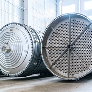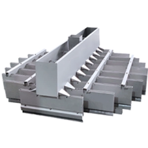
A devolatilizer vacuum system must maintain the required absolute pressure while handling process vapors, noncondensable gases, and potential contaminants. Its design affects volatile removal, product quality, energy consumption, and continuous operating reliability.
Selecting a suitable system requires engineers to calculate the gas load at actual operating conditions, account for pressure losses, evaluate condensation and separation requirements, and assess how deposits may affect long-term performance. These factors determine whether steam-jet ejectors, liquid-ring pumps, dry vacuum pumps, or hybrid configurations are appropriate for a particular process.
What Determines Devolatilizer Vacuum System Requirements?
The main design inputs are the required absolute pressure, gas and vapor load, composition, operating temperature, pressure losses, and expected process variability. These inputs establish the capacity required from the vacuum equipment and the conditions under which it must operate.
Establish the Pressure Budget
The pressure inside the devolatilizer may be higher than the pressure at the vacuum equipment inlet because gas flowing through vapor lines, separators, condensers, and other components encounters pressure losses.
For a simplified system with a defined gas-flow direction, the relationship is
P_{\mathrm{vacuum\ inlet}}+\sum_i \Delta P_i]
where (P_{\mathrm{devolatilizer}}) is the absolute pressure inside the devolatilizer, (P_{\mathrm{vacuum\ inlet}}) is the absolute pressure at the vacuum equipment inlet, and (\Delta P_i) represents the pressure loss across each intervening component.
For example, if the devolatilizer requires 10 kPa absolute pressure and the intervening equipment produces a combined pressure loss of 2 kPa, the vacuum equipment inlet must operate at approximately 8 kPa absolute under those conditions.
This is a simplified pressure-budget example, not a universal design specification. Pressure losses must correspond to the actual operating load and local gas conditions. Condensation can change gas composition and volumetric flow, so calculations across a condenser should use the appropriate upstream and downstream conditions.
Engineers should identify the pressure measurement locations needed to distinguish losses across individual components. A pressure difference between the devolatilizer and the vacuum equipment inlet does not, by itself, identify which component causes the loss.
Calculate Gas Capacity at Actual Conditions
Vacuum pump selection must distinguish pumping speed, mass flow rate, and standard-state volumetric flow rate. These quantities describe different aspects of gas handling and cannot be substituted for one another without conversion.
For an ideal gas,
[\dot V = \frac{\dot m RT}{MP}]
where (\dot V) is volumetric flow rate, (\dot m) is mass flow rate, (R) is the universal gas constant, (T) is absolute temperature, (M) is molecular weight, and (P) is absolute pressure. All quantities must use a consistent set of units.
The equation illustrates why the same gas mass flow occupies a larger volume at lower pressure. For multicomponent vapor streams, engineers must use appropriate mixture properties and account for changes in composition and flow as condensation occurs.
The required gas load should include the expected contributions from residual monomers, solvents, water vapor, reaction byproducts, stripping gases, and air leakage. Normal production, maximum credible load, and relevant startup or transient conditions should be evaluated separately.
A pump’s ultimate vacuum rating does not establish its capacity at the required process pressure. Selection must use manufacturer performance data for the actual inlet pressure, temperature, gas composition, and load.
Establish the Design Cases
The design basis should distinguish normal production from operating conditions that can materially change the required capacity.
| Design case | Key considerations |
|---|---|
| Normal production | Expected vapor load, pressure, temperature, and production rate |
| Maximum credible load | Peak vapor generation, feed composition changes, or increased stripping-gas flow |
| 시작 및 종료 | Transient vapor loads, changing temperatures, and evacuation requirements |
| Disturbed operation | Foaming, entrainment, leakage, or temporary process changes |
| Long-term operation | Fouling, increasing pressure losses, maintenance, and performance deterioration |
The design margin should reflect uncertainty in process data and the consequences of losing vacuum. Excessive oversizing can increase capital cost and complicate control, while insufficient capacity can compromise process pressure and throughput.
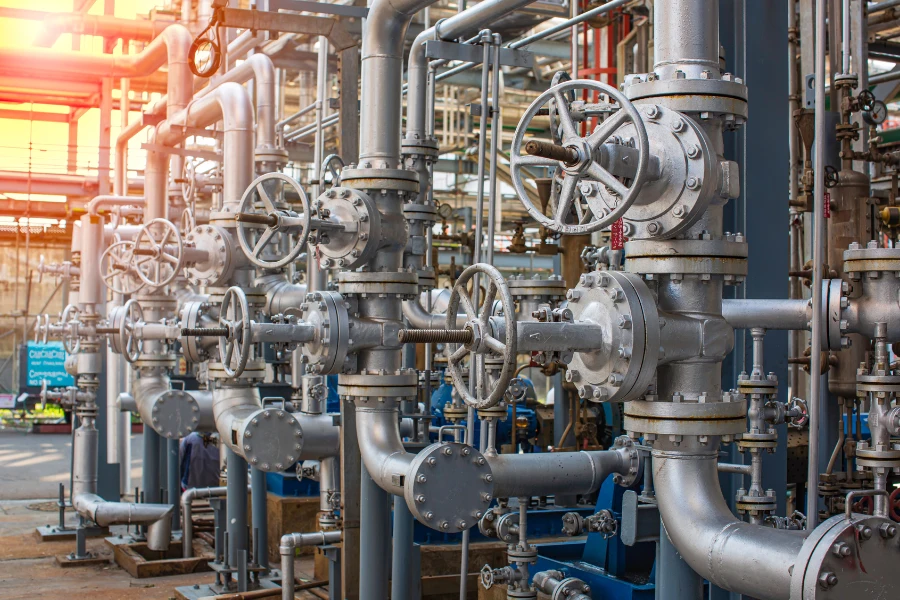
How to Select a Vacuum System for Devolatilization
The selection process should first eliminate configurations that cannot meet the required pressure or gas capacity. The remaining options should be compared by utility demand, condensation behavior, contamination risk, maintenance requirements, and downstream recovery needs.
Steam-Jet Ejectors
Steam-jet ejectors use a high-velocity motive steam jet to entrain and compress process gas and vapor. Because the ejector has no moving mechanical components, it can offer relatively simple mechanical maintenance and may suit certain wet or contaminated gas streams.
Its operating performance depends on motive steam pressure and condition, suction pressure, gas load, and the downstream system. Steam consumption, cooling requirements, and condensate handling must be evaluated together.
A steam ejector may be attractive where suitable steam is readily available. Its economic advantage can diminish when steam is expensive, cooling capacity is limited, or contaminated condensate requires additional treatment.
Multistage arrangements should be assessed as complete systems, including intercondensers, aftercondensers, and discharge handling where applicable. Cooling-water temperature and condenser performance affect the amount of vapor removed between stages and the load reaching downstream equipment.
The required capacity at the minimum process pressure is a primary selection criterion.
Liquid-Ring Vacuum Pumps
Liquid-ring pumps use a rotating impeller and a sealing liquid to compress gas. They may suit applications involving moisture or certain contaminated gas streams, provided the sealing liquid and operating conditions are compatible with the process.
The achievable vacuum depends partly on sealing-liquid temperature and vapor pressure. Warmer sealing liquid can limit vacuum performance, while absorbed or condensed process components can complicate liquid treatment, solvent recovery, and disposal.
The selection assessment should include electricity, sealing-liquid circulation, cooling, separation, and treatment requirements. A liquid-ring system may be less attractive when the required pressure is difficult to achieve under the available liquid conditions or when contaminated sealing liquid creates substantial handling costs.
Dry Vacuum Pumps
Dry vacuum pumps compress gas without intentionally introducing a sealing liquid into the pumping chamber. Depending on the pump design, they may reduce liquid-handling requirements and avoid contamination associated with a sealing liquid.
Dry operation does not eliminate fouling risk. Condensable vapors may form liquid deposits inside the pump, while polymer carryover, solidified components, or reaction products can restrict internal passages.
Engineers should evaluate the specific pump technology, inlet temperature, vapor composition, purge requirements, contamination tolerance, and cleaning provisions. Dry screw and claw pumps should not be assumed to have identical performance or contamination tolerance.
A dry pump may be unsuitable without additional protection when the process stream contains components that condense or react under its internal operating conditions.
Roots Boosters and Hybrid Systems
Roots vacuum boosters are often combined with backing pumps to improve pumping capacity over a defined pressure range. Their suitability depends on the required pressure, gas load, allowable pressure ratio, temperature rise, motor load, and backing-pump performance.
A booster cannot compensate for inadequate condensation or uncontrolled contaminant carryover. The complete combination must be checked against the operating envelope specified by the equipment manufacturer.
Hybrid systems can combine ejectors, mechanical pumps, condensers, and separation equipment. They are worth evaluating when one technology cannot meet the process requirements efficiently, but the additional equipment must justify its capital, energy, and maintenance costs.
Compare Technologies Against the Process
| 선정 요인 | Steam-jet ejector | Liquid-ring pump | Dry vacuum pump | Roots booster with backing pump |
|---|---|---|---|---|
| Primary energy input | Motive steam | Electricity | Electricity | Electricity |
| Main utility considerations | Steam, cooling, condensate handling | Electricity, sealing liquid, cooling | Electricity and auxiliary services | Electricity for the booster and backing pump |
| Condensable vapor | Depends on staging and condensation arrangement | Depends on liquid conditions and gas composition | Depends on pump design and vapor handling | Depends on both pumps and upstream vapor handling |
| Main contamination concerns | Deposits, erosion, downstream handling | Sealing-liquid contamination and deposits | Internal condensation, polymer deposits, solids | Contamination affecting either the booster or backing pump |
| Key selection evidence | Performance curves, steam conditions, and condenser performance | Performance data at actual pressure and liquid temperature | Performance data and process compatibility | Combined performance curves and allowable operating range |
This table supports preliminary screening rather than final equipment selection. Engineers should confirm that the proposed system can maintain the required absolute pressure at the maximum credible gas load, that upstream condensation is feasible, and that the remaining vapor is compatible with the selected equipment.
Steam, electricity, cooling availability, solvent recovery, and emissions treatment must also be included in the comparison. Final selection requires manufacturer performance data and process-specific calculations.
How to Calculate Devolatilizer Vacuum System Energy Consumption
Energy comparisons require a consistent system boundary. Pump power or steam consumption alone may not represent the total energy required to maintain vacuum and handle the extracted vapor.
Distinguish Energy Consumption From Operating Cost
Different metrics answer different engineering questions.
| Assessment | Required data | Result |
|---|---|---|
| Equipment energy | Measured power, steam flow, operating time | kWh or steam consumption per operating period |
| System energy | Vacuum equipment and relevant auxiliary loads | Total energy within the defined boundary |
| Specific energy consumption | System energy and acceptable product output | kWh/t or MJ/t |
| Specific operating cost | Utility prices, energy use, maintenance, and product output | Cost per ton of saleable product |
The system boundary may include vacuum pumps, boosters, motive steam, condensers, cooling-water pumps, cooling systems, sealing-liquid circulation, and vapor recovery or off-gas treatment. The same boundary must be used when comparing alternative configurations.
Condenser heat duty must be distinguished from cooling-system energy consumption. Heat duty measures the heat removed from the process, while cooling-system energy measures the electricity or other energy used to provide that cooling. Where a 열교환기 is used for process cooling or condensation, its thermal performance and associated utility demand should be evaluated within the same system boundary.
Calculate Electricity Consumption
For a varying electrical load,
\int_{t_0}^{t_1}P(t),dt]
where (P(t)) is measured electrical power and the time interval covers the operating period being assessed.
For stable operation, average power multiplied by operating time may be sufficient. Motor nameplate power should not be treated as actual consumption when measurements or reliable operating estimates are available.
Startup, shutdown, and cleaning periods should be included in annual operating estimates when they materially affect total consumption.
Account for Steam and Other Utilities
Steam ejectors require a separate accounting method because steam is often measured by mass rather than electrical energy. Steam mass cannot be added directly to kWh or MJ without conversion.
The calculation must define the steam state and energy reference. Depending on the purpose, the assessment may use a specified enthalpy basis or another documented method for accounting for the energy associated with the steam supply.
For operating-cost comparisons, apply the actual cost of each utility separately. Include the electricity used by cooling and circulation equipment, as well as other relevant auxiliary loads.
For comparisons based on total energy, convert different energy sources to a common unit using documented assumptions. For operating-cost comparisons, retain the actual cost of each utility rather than mixing energy quantities with monetary values.
Calculate Specific Energy Consumption
Specific energy consumption measures total energy against the mass of acceptable product produced during the same period.
\frac{E_{\mathrm{total}}}{M_{\mathrm{product}}}]
Here, (E_{\mathrm{total}}) is the energy consumed within the defined boundary, converted to a consistent unit if multiple energy sources are combined, and (M_{\mathrm{product}}) is the mass of saleable product meeting the required specification.
A corresponding operating-cost metric is
\frac{C_{\mathrm{energy}}+C_{\mathrm{maintenance}}}
{M_{\mathrm{product}}}]
where the cost terms cover the same assessment period as the product output. Capital costs can be evaluated separately when comparing lifecycle economics.
For a practical assessment, record actual vacuum equipment power, steam flow and state, auxiliary equipment energy, production rate, product quality, utility prices, and maintenance expenses. This dataset supports comparisons in kWh/t, MJ/t, or currency per ton without mixing energy quantities and costs.
Identify the Dominant Energy Load
Energy reduction should target the measured process limitation.
- Excessive gas load. Check air leakage and stripping-gas flow. Reducing unnecessary gas input can lower the load without directly compromising volatile removal.
- Insufficient condensation. Evaluate vapor composition, condenser temperatures, cooling conditions, and condensate flow. Better condensation may reduce downstream pumping demand, although the additional cooling requirement must be counted.
- Poor equipment matching. Compare actual pressure and gas load with equipment performance data. A system operating outside its intended range may consume unnecessary energy or fail to maintain the required pressure.
- Fouling. Investigate whether deposits increase pressure loss or reduce heat-transfer performance. Correcting the deposition mechanism may be more effective than repeatedly cleaning the equipment.
- Mass-transfer limitations. If volatile removal is limited by poor melt distribution, insufficient interfacial area, or internal diffusion, increasing vacuum capacity alone may not improve product quality.
Any proposed improvement should be evaluated against total system energy, throughput, and residual-volatile concentration. Lower electricity consumption is not necessarily an improvement if it increases other utility demand or reduces acceptable product output.
Fouling Mechanisms in Devolatilizer Vacuum Systems
Deposits in a devolatilization system can form through phase changes, crystallization, or chemical reactions. Entrained polymer droplets and particles provide a separate transport pathway that can carry material into downstream equipment.
Identifying the mechanism and the location of deposition is necessary to select an appropriate control measure.
Condensation and Solidification
A vapor component may condense when local temperature, pressure, and composition permit liquid formation. The liquid may subsequently solidify if the local conditions favor a solid phase.
Deposits can accumulate in cooler sections of vapor piping or on condenser surfaces when the phase behavior of the stream permits it. The resulting restriction can increase pressure losses and interfere with vapor transport.
The design should establish where condensation is intended to occur and provide suitable drainage and condensate collection. Uncontrolled condensation upstream of the intended separation stage may increase blockage and contamination risk.
침전 및 결정화
Precipitation fouling may occur when a dissolved component becomes supersaturated and crystallizes on a surface. Its relevance depends on the actual process composition, solubility, concentration, and temperature conditions.
Where crystallization is plausible, investigate concentration changes and local operating conditions before selecting a control measure. Temperature management, composition control, material selection, or cleaning may be appropriate depending on the identified mechanism.
Reaction-Induced Deposits
Some process components may react or polymerize under the temperatures, residence times, and chemical conditions present in the vapor-handling system. Reaction-induced deposits can adhere to surfaces and become more difficult to remove as they age or undergo further reaction.
Potential contributing conditions include excessive thermal exposure, local overheating, oxygen ingress where oxidation is relevant, and stagnant regions that retain reactive material. These factors must be checked against the actual process chemistry.
Lowering temperature may reduce some reaction risks but can promote condensation or solidification elsewhere. The temperature profile must therefore be evaluated across the entire vapor path.
Polymer Melt Entrainment
Polymer melt entrainment is a transport mechanism rather than a deposition mechanism in itself. Droplets, foam, or fine material carried out of the devolatilizer may reach downstream equipment and form deposits.
The risk depends on the material’s foaming behavior, gas velocity, pressure reduction, vapor-space geometry, and separation performance. Potential controls include adequate vapor disengagement, suitable entrainment separation, and stable melt distribution.
A gas-liquid separator may be appropriate when the process requires dedicated separation of entrained liquid from a gas stream. Its suitability depends on droplet characteristics, gas load, pressure-drop allowance, drainage requirements, and contamination profile.
A demister may remove entrained droplets but will not necessarily prevent vapor condensation downstream. Separation equipment must match the material being carried over and the mechanism responsible for contamination.
Identify Deposits by Location
| Location | Possible mechanism or transport route | Evidence to investigate |
|---|---|---|
| Vapor-line walls | Condensation, solidification, crystallization, reaction | Wall temperature, pressure loss, deposit composition |
| Condenser surfaces | Condensation-related deposits, precipitation, reaction, polymer carryover | Cooling conditions, temperature approach, deposit analysis |
| Knockout vessels and separators | Liquid accumulation, entrainment, solids deposition | Liquid level, drainage, separator loading |
| Vacuum pump inlet | Entrained droplets, condensed vapor, particles | Inlet conditions, upstream separation, condensate observations |
| Internal pump passages | Condensation, solidification, reaction-related deposits | Pump temperature, inspection findings, process compatibility |
These are possible causes, not definitive assignments. Deposit composition, operating trends, and inspection findings should be used to confirm the mechanism before the process or equipment design is changed.
How to Prevent Fouling and Troubleshoot Vacuum Performance Loss
Fouling control should begin with operating evidence that identifies where performance is deteriorating. Cleaning may restore performance temporarily, but recurring deposits require investigation of their formation conditions.
Diagnose the Cause From Operating Trends
Pressure, temperature, flow, condensate, and energy measurements should be interpreted together.
| Operating signal | 가능한 원인 | Next verification step |
|---|---|---|
| Devolatilizer pressure rises while vacuum equipment inlet pressure remains stable | Increased pressure loss across piping, a separator, or a condenser | Compare intermediate pressure measurements to locate the additional pressure drop |
| Gas load downstream of a condenser increases | Higher inlet vapor load, reduced condensation, or changed process conditions | Check inlet load, cooling conditions, outlet temperature, and condensate rate |
| Vacuum pressure fluctuates while condensate load rises sharply | Transient flashing, foaming, entrainment, or condenser overload | Compare feed rate, temperature, pressure, liquid level, and condensate trends |
| Performance improves after cleaning but gradually deteriorates again | Recurring deposition or an unresolved operating limitation | Examine deposit composition, location, operating conditions, and time between cleanings |
| Pump power rises without a corresponding increase in product throughput | Increased gas load, altered operating pressure, equipment deterioration, or other operating changes | Compare gas load, pressure, power, cooling, and equipment condition against the baseline |
These relationships are diagnostic hypotheses rather than one-to-one fault assignments. Multiple measurements are needed to distinguish process changes from equipment deterioration.
Control Condensation and Protect Vacuum Equipment
The vapor path should direct condensation to equipment designed to collect and remove the resulting liquid. Where condensation upstream of the intended separation stage would create blockage, review the temperature profile, vapor composition, and drainage arrangements.
Vacuum equipment should not be expected to handle bulk condensate or polymer droplets unless it is specifically designed for that service. Depending on the process, protection may include a vapor disengagement space, knockout vessel, demister, condenser, or other appropriate 분리 장비.
Each component must be checked for vapor load, separation performance, pressure drop, drainage, and cleaning access. Excessive pressure loss across protective equipment can undermine the required process pressure, while inadequate separation can expose downstream equipment to contaminants.
Establish Cleaning Intervals From Operating Evidence
Cleaning intervals should reflect the observed fouling rate and the consequences of performance loss. A fixed schedule may be appropriate when operating experience shows repeatable deposit formation, but elapsed time alone is insufficient when process loads vary significantly.
Use pressure-loss trends, condenser performance, residual-volatile results, inspection findings, and cleaning history to determine when intervention is required. Record deposit location and composition where available, the cleaning method, and performance after restart.
Repeated deposits at the same location may indicate a persistent problem with temperature, flow distribution, phase behavior, or separation. The maintenance strategy should address that cause rather than relying only on more frequent cleaning.
Pilot Testing and Industrial Scale-Up
Pilot testing should verify that the complete vacuum system can maintain the required pressure and handle representative vapor loads under continuous operating conditions. Short tests may establish initial performance but cannot necessarily demonstrate long-term resistance to fouling.
Validate Capacity and Operating Stability
Use representative feed material or a model system whose limitations are understood. Relevant variables include volatile composition, feed concentration, viscosity, temperature, throughput, stripping-medium rate, and operating pressure.
Testing should cover normal production and credible peak loads. Startup or grade transitions should be evaluated separately when they materially affect the required capacity.
Where fouling is a credible risk, record pressure losses, condenser performance, deposit formation, condensate quality, and the time required for performance to deteriorate. Assess whether cleaning restores performance and whether deposits recur under the same conditions.
Define Acceptance Criteria Before Testing
The project team should establish measurable acceptance criteria appropriate to the process. These may include:
- Required absolute pressure at the specified production rate.
- Maximum credible gas load handled by the system.
- Residual-volatile concentration in the product.
- Specific energy consumption at a defined production rate.
- Acceptable pressure losses across vapor-handling equipment.
- Performance stability over a representative operating period.
- Fouling behavior and cleaning requirements over that period.
The test duration should reflect the expected fouling mechanism. A short run may confirm initial capacity but cannot establish a reliable long-term cleaning interval if deposits develop slowly.
The commercial design should be based on verified process data, equipment performance, and an explicit assessment of remaining uncertainty. Projects requiring integrated process assessment can also explore DODGEN’s 프로세스 기술 솔루션.
Devolatilizer Vacuum System Selection Checklist
Before requesting quotations or finalizing equipment selection, establish the following information.
| Design area | Required information |
|---|---|
| 공정 목표 | Target residual-volatile concentration and product specification |
| Feed material | Composition, viscosity, temperature, and thermal stability |
| Volatile load | Component identity, concentration, flow rate, and variability |
| Pressure requirements | Target absolute pressure and allowable fluctuations |
| Gas capacity | Normal and peak loads, noncondensables, leakage, and stripping-gas flow |
| 응축 | Expected condensable fraction, cooling conditions, and condensate handling |
| Contamination | Potential for condensation, crystallization, reaction-induced deposits, and polymer entrainment |
| Utilities | Electricity, steam, cooling, and other required services |
| Environmental controls | Solvent recovery, off-gas treatment, and applicable emissions requirements |
| 유지 관리 | Inspection access, cleaning method, and spare parts |
| Validation | Pilot test plan, energy measurements, performance criteria, and scale-up requirements |
These inputs allow engineers to compare vendor proposals against the same process basis and identify uncertainties that must be resolved before final equipment sizing.
Engineering Support for Devolatilization Projects
도겐 supports process evaluation, equipment integration, and pilot-to-commercial scale-up for high-viscosity material processing and devolatilization applications.
For projects with demanding residual-volatile targets or recurring vacuum-system problems, the engineering assessment should begin with the feed properties, vapor load, pressure requirements, utility conditions, and observed operating limitations. These inputs provide the basis for evaluating vacuum generation, condensation, separation, and contamination control as an integrated system.
Discuss your process requirements with DODGEN to evaluate a suitable devolatilization and vacuum-system configuration.