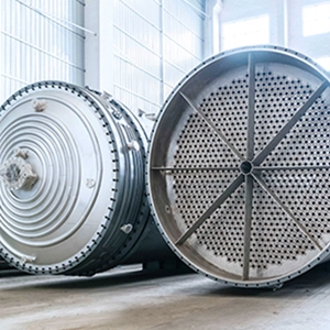
Fouling in a falling film evaporator adds thermal resistance, can restrict liquid flow and may reduce evaporation capacity. The resulting production constraints depend on deposit composition, liquid distribution, operating conditions and the available performance margin before cleaning becomes necessary.
An effective cleaning strategy links online monitoring to maintenance decisions. Engineers need to identify the likely fouling mechanism, estimate how quickly performance is deteriorating, select an appropriate cleaning method and verify recovery against a reliable clean-state baseline.
What Causes Fouling in Falling Film Evaporators?
A evaporador de película descendente distributes liquid over heated surfaces, typically inside vertical tubes. The liquid flows downward as a thin film while heat transferred through the wall evaporates part of the process stream and increases the concentration of the remaining liquid.
Fouling develops when dissolved substances precipitate, organic materials accumulate or inadequate liquid distribution creates poorly wetted surfaces. These mechanisms can coexist, but their relative importance depends on the process fluid and operating conditions.
Crystallization and Mineral Scale Formation
Crystallization fouling occurs when dissolved substances exceed their local solubility limits. As evaporation concentrates the liquid, changes in temperature and composition can promote precipitation on heat-transfer surfaces.
Deposit composition determines how readily scale can be removed. Calcium-containing deposits, sulfates, carbonates and silicates differ in solubility, hardness and structure. Some form relatively soft layers, while others create compact deposits that resist mechanical removal.
In multieffect evaporators, deposit composition and hardness may vary between effects as temperature, concentration and liquid chemistry change. A uniform cleaning procedure may therefore be less effective than a strategy tailored to the deposit and equipment geometry in each section.
Organic Deposits and Thermal Degradation
Organic fouling can occur when product components accumulate, degrade or undergo further reactions near heated surfaces. In sugar processing, prolonged thermal exposure during abnormal operating conditions can increase the amount of caramelized material in deposits.
In polymer processing, residual monomers, oligomers, increasing viscosity and continued reactions near the heat-transfer wall may contribute to fouling. Deposit aging can also make removal more difficult.
The cleaning method must match the dominant deposit mechanism. A procedure suitable for mineral scale should not automatically be applied to organic or polymer-rich deposits without evaluating chemical compatibility and removal effectiveness.
Poor Liquid Distribution and Inadequate Tube Wetting
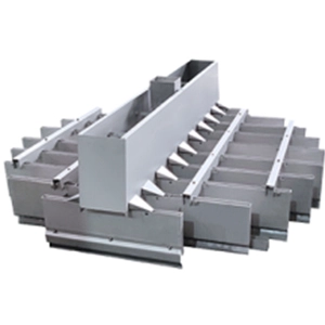
Blocked distributor holes, unsuitable distributor geometry or insufficient liquid loading can leave parts of the heat-transfer surface poorly wetted even when total feed flow appears adequate. Localized dry regions can promote deposit formation and reduce effective heat transfer.
As deposits accumulate, flow distribution may deteriorate further, creating a cycle of restricted wetting and additional fouling. Upstream solids or obstructions can contribute by blocking distributor openings.
Minimum wetting conditions depend on fluid properties, surface characteristics, equipment geometry and the operating regime. For concentrated products with non-Newtonian behavior, a constant-viscosity assumption may not adequately describe the flow.
Cleaning can remove accumulated deposits, but recurring maldistribution requires investigation of the distributor, feed conditions and upstream process.
Because distributor geometry and tube-bundle configuration influence both liquid wetting and cleaning access, these design features should be evaluated alongside the cleaning procedure. DODGEN’s evaporador de película descendente integrates liquid distribution, heat-transfer and auxiliary cleaning systems into the equipment design.
How Fouling Affects Heat Transfer and Evaporation Performance
Deposits introduce additional thermal resistance between the heating medium and the process liquid. Under otherwise comparable conditions, increasing fouling resistance generally reduces the overall heat-transfer coefficient (HTC), potentially lowering evaporation capacity or increasing utility demand.
Calculating the Overall Heat-Transfer Coefficient
The overall heat-transfer coefficient can be estimated from the heat-transfer rate, effective heat-transfer area and logarithmic mean temperature difference.
[U=\frac{Q}{A\Delta T_{\mathrm{lm}}}]
Dónde:
- (U) is the overall heat-transfer coefficient.
- (Q) is the heat-transfer rate.
- (A) is the effective heat-transfer area.
- (\Delta T_{\mathrm{lm}}) is the logarithmic mean temperature difference.
A simplified thermal-resistance relationship is:
[\frac{1}{U}=R_{\mathrm{process}}+R_{\mathrm{wall}}+R_{\mathrm{utility}}+R_f]
Here, (R_f) represents the additional thermal resistance attributed to fouling under the selected model.
Where a representative clean baseline exists, apparent fouling resistance can be estimated as:
[R_{f,\mathrm{app}}=\frac{1}{U_{\mathrm{current}}}-\frac{1}{U_{\mathrm{clean}}}]
This estimate requires the same heat-transfer area basis and sufficiently comparable operating conditions, or corrections for other changes. It represents an apparent resistance derived from performance data, not a direct measurement of deposit thickness.
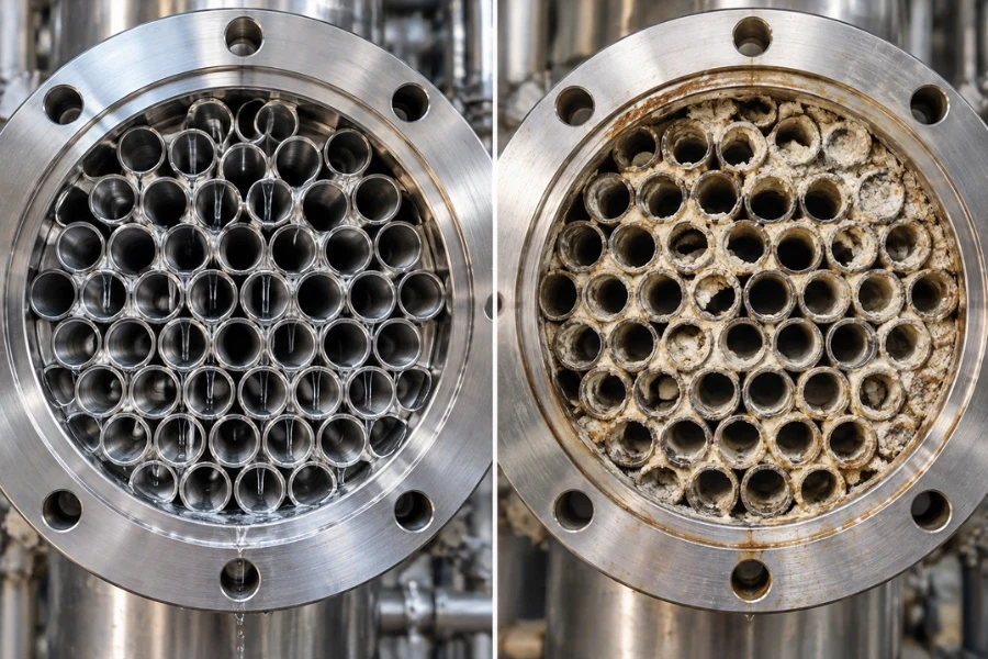
Changes in flow, viscosity, vapor conditions, temperature measurements or utility-side performance can also affect HTC. A decline is therefore a diagnostic signal, not proof of fouling by itself.
Combining Heat Transfer and Pressure Drop
HTC and pressure drop provide complementary information. A thin deposit may increase thermal resistance before significantly restricting flow, while localized buildup can cause a substantial pressure-drop increase.
| Operating observation | Possible interpretation | Recommended action |
|---|---|---|
| HTC declines gradually, pressure drop remains stable and production meets requirements | Increasing thermal resistance or changing heat-transfer conditions | Verify comparable operating conditions, check instrumentation and continue trend monitoring |
| HTC declines consistently and is projected to approach its acceptable lower limit | Fouling may constrain production before the next maintenance window | Estimate the remaining operating window and prepare a cleaning plan |
| HTC declines while pressure drop rises | Thermal deterioration and flow restriction may be developing together | Investigate deposits, blocked passages and liquid distribution |
| HTC changes abruptly without a corresponding change in other indicators | A process disturbance or measurement issue may be involved | Check feed composition, flow, temperature, vapor conditions and instrumentation |
| La caída de presión aumenta rápidamente | Localized restriction or flow redistribution may be occurring | Review operating conditions and inspect accessible sections where appropriate |
| HTC remains below the clean baseline after cleaning | Residual deposits or another unresolved constraint may remain | Check cleaning coverage, distributor condition, utilities and measurement reliability |
These patterns guide diagnosis but do not establish the cause independently. Interpretation depends on equipment configuration, process fluid and measurement reliability.
Online Monitoring of Falling Film Evaporator Fouling
Online monitoring helps operators identify performance deterioration during production. The most useful approach combines a verified clean-state baseline with measurements collected under comparable operating conditions.
Establishing a Clean-State Baseline
After cleaning and performance verification, record the operating conditions associated with acceptable performance. Depending on the system, these may include:
- Feed and concentrate flow rates.
- Feed, process and heating-medium temperatures.
- Vapor pressure and operating vacuum.
- Heating-medium flow and pressure.
- Product concentration or dry-solids content.
- Pressure drop across relevant sections.
- Evaporation rate and production throughput.
- Calculated HTC.
Where operating conditions vary significantly between production campaigns, use separate reference states or a suitable normalization method. Comparing measurements from substantially different operating conditions can produce misleading fouling trends.
Review the baseline after major process changes or equipment modifications.
Using HTC Trends to Support Cleaning Decisions
HTC trends can reveal gradual performance deterioration, but the observed rate must be interpreted in context.
When analyzing the trend, distinguish the current HTC from its rate of change. A steadily declining HTC may allow planned maintenance, while an accelerating decline can shorten the available operating window. Both must be evaluated against the process’s acceptable performance limit.
A linear trend can support short-term forecasting when the data justify that assumption. It should not be extrapolated indefinitely because deposit formation and operating conditions can change over time.
Estimating the Remaining Operating Window
When historical data support a reasonably stable deterioration trend, engineers can estimate the time remaining before HTC reaches an operating limit.
[t_{\mathrm{remaining}}=\frac{U_{\mathrm{current}}-U_{\mathrm{limit}}}{r_U}]
Dónde:
- (U_{\mathrm{current}}) is the current normalized HTC.
- (U_{\mathrm{limit}}) is the minimum acceptable HTC.
- (r_U) is the estimated HTC decline rate, expressed as a positive value.
Use this estimate only when the observed decline is sufficiently stable and the operating conditions remain comparable. Recalculate the estimate when the trend accelerates, process conditions change or measurement uncertainty becomes significant.
The result is a planning estimate, not a guaranteed time to failure. The cleaning date should also account for maintenance availability, production schedules and an appropriate operational margin.
Confirming the Diagnosis Through Inspection
Online measurements show how performance changes but do not necessarily identify deposit composition or location.
Where the equipment design permits, sight glasses can help operators observe liquid distribution or the movement of installed cleaning mechanisms. Shutdown inspections can reveal blocked distributor holes, tube obstructions and deposit accumulation.
Deposit analysis can distinguish mineral scale from organic or mixed deposits. Where an appropriate online cleaning arrangement allows wash-liquid collection, analysis of the recovered material may also help identify the dominant deposit components.
The diagnosis should combine operating trends with physical evidence where available. This reduces the risk of treating a distribution or utility problem as a fouling problem.
How to Determine the Mechanical Cleaning Cycle
The cleaning cycle should reflect fouling behavior, equipment limits, production requirements and the cost of continued operation.
Fixed intervals are useful when operating conditions and fouling rates are repeatable. When feed composition, concentration or throughput varies, condition-based cleaning can respond more directly to actual performance. A hybrid strategy can combine operating thresholds with planned maintenance windows, provided continued operation remains within acceptable limits.
Defining Process-Specific Cleaning Triggers
Potential cleaning triggers include:
- Normalized HTC approaching its acceptable lower limit.
- Apparent fouling resistance exceeding a validated threshold.
- Pressure drop approaching a hydraulic or equipment limit.
- Difficulty maintaining the required product concentration.
- Utility demand becoming economically unfavorable.
- Throughput or process stability becoming constrained.
- A deterioration trend indicating that an operating limit may be reached before the next maintenance window.
A fixed percentage decline in HTC can be evaluated as a candidate trigger, but it is not a universal standard. The acceptable limit depends on equipment design, process requirements, measurement uncertainty and available production margin.
Setting an Automated Mechanical Cleaning Cycle
An automated mechanical cleaning cycle must coordinate the trigger condition, cleaning sequence, operating duration, interval between cycles and post-cleaning verification. The correct settings depend on the installed cleaning mechanism, heat-transfer surface, deposit properties and the equipment’s ability to discharge removed solids.
1. Define the trigger condition. A PLC may initiate cleaning on a validated time schedule, in response to an operating condition or through a hybrid strategy. A fixed schedule can suit repeatable operating conditions, while performance-based triggers may be more appropriate when fouling rates vary. Any automatic trigger should operate within approved process and equipment limits.
2. Set the cleaning sequence. Where several nozzles or cleaning units serve different sections, the control logic should define whether they operate sequentially or simultaneously. Sequential operation can help manage shared water or utility capacity and reduce simultaneous demand. The actual arrangement must be confirmed against the installed system’s hydraulic and mechanical design.
3. Establish the active duration and interval. The PLC program should specify how long each cleaning unit operates, how long the system waits before moving to the next unit and how long it waits before starting another cycle. These values must be established through equipment requirements, commissioning and operating evidence rather than copied from another installation.
4. Confirm cleaning coverage and solids discharge. The sequence must reach the intended heat-transfer surfaces and provide a route for dislodged material to leave the equipment. If the cleaning mechanism moves deposits but the discharge path cannot carry them away, material may accumulate in restrictions or downstream equipment.
5. Monitor completion and faults. Where suitable instrumentation is available, the control system can monitor valve feedback, pressure or flow conditions, cycle completion and relevant process alarms. Missing feedback, abnormal pressure, insufficient flow or repeated incomplete cycles should trigger the configured alarm and inspection procedure. Operators should not assume that a command to clean proves that cleaning occurred.
6. Verify the result. After the cycle, compare relevant performance indicators with their expected trends. A stable HTC, acceptable pressure drop and maintained evaporation duty can support continued operation, but the interpretation must account for process conditions and measurement uncertainty. If performance continues to deteriorate, investigate the cleaning coverage, deposit characteristics, distributor condition and discharge path before simply increasing cycle frequency.
Example of a PLC-Controlled Cleaning Sequence
One equipment-specific program described in the supplied reference material uses three cleaning units. Unit F101 operates for 10 seconds, followed by a 120-second interval. F102 then operates for 10 seconds, followed by another 120-second interval, before F103 operates for 10 seconds. After the sequence is complete, the program waits 180 minutes before restarting the cycle.
These values illustrate how a timed, sequential cleaning program can be organized. They are not universal design parameters or a recommended starting point for every falling film evaporator. Actual cycle duration, waiting intervals, nozzle pressure and trigger logic must be validated for the installed equipment and process.
Deciding When to Shorten the Cycle or Stop for Inspection
A scheduled cycle should be reviewed when performance deteriorates faster than expected, the same sections repeatedly foul, cleaning faults occur or post-cleaning recovery declines.
Shortening the interval may be appropriate when the cleaning mechanism is effective but deposits accumulate between cycles. It is less likely to solve a problem caused by poor liquid distribution, unsuitable cleaning coverage, a blocked discharge path or deposits that the selected method cannot remove.
Stop or isolate the system according to the approved operating procedure when a fault creates an unacceptable safety or equipment risk. Abnormal cleaning pressure, failed valve feedback, leakage, unexpected vibration or persistent flow restriction should not be addressed simply by repeatedly restarting the cleaning program.
Mechanical Cleaning Methods and Their Limitations
Mechanical cleaning physically dislodges or removes deposits. Clean-in-place (CIP) circulates a cleaning solution through the equipment without full disassembly, relying on chemical action and suitable contact conditions. Some systems use both approaches.
Method selection should account for deposit composition and hardness, equipment geometry, tool access, material compatibility, safety requirements and the ability to remove loosened solids.
Selecting a Method Based on Deposit Properties
Relatively soluble or loosely attached deposits may respond to a validated CIP procedure. Hard, compact deposits that resist suitable chemical cleaning may require mechanical removal, provided the equipment allows safe access.
For narrow, misaligned or complex passages, confirm that a brush, scraper, drilling tool or water-jet nozzle can reach the affected surface without damaging the equipment. Where loosened material cannot be reliably collected and discharged, the cleaning strategy must address that limitation before the method is selected.
These considerations are especially important in multieffect systems, where deposit composition, hardness and accessibility may differ between effects. A cleaning method that works in one section may not be suitable for another.
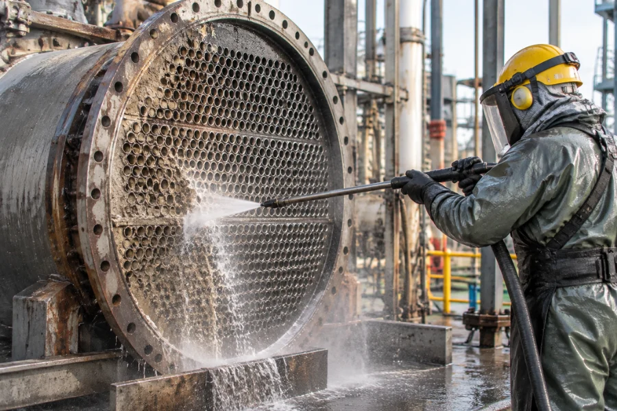
High-Pressure Water Jet Cleaning
High-pressure water jetting can remove deposits that resist ordinary flushing, but effectiveness depends on deposit properties and access to the affected surface.
Engineers should assess nozzle access, tube alignment, opening dimensions and the route for discharging dislodged solids. A jet may clean an accessible section while leaving deposits in narrow or misaligned passages.
Pressure and nozzle configuration must follow equipment requirements and an approved safety procedure. Excessive mechanical force can damage tubes, heat-transfer surfaces, seals or other components. The cleaning plan should also prevent removed solids from accumulating in downstream equipment.
Brushes, Scrapers and Specialized Mechanical Devices
Brushes, scrapers and other mechanical tools may be suitable when the equipment provides sufficient access and the deposits respond to physical removal.
Their effectiveness depends on deposit hardness, passage geometry, material strength and tool reach. A tool designed for a straight, accessible tube may not work in a narrow or misaligned assembly.
The procedure should specify tool selection, acceptable contact forces, inspection requirements and how loosened material will be removed. If the tool cannot reach the affected surface reliably, another method may be required.
Pressure-Pulse Cleaning for Applicable Designs
Some specialized polymer-film heat exchangers use pressure pulses to move a flexible heat-transfer surface and displace rigid deposits. The falling liquid film can then carry the detached material away.
This method depends on the flexibility of the heat-transfer surface, deposit properties and the equipment’s ability to discharge solids. It is specific to suitable designs and should not be assumed to apply to conventional rigid-tube evaporators without confirming the equipment configuration and approved operating procedure.
Mechanical Cleaning vs. Chemical Cleaning
Mechanical cleaning is not a universal replacement for CIP. Mineral scale, organic deposits and mixed fouling layers may respond differently to physical and chemical removal.
| Consideration | Limpieza mecánica | Chemical cleaning or CIP |
|---|---|---|
| Primary mechanism | Physical dislodging or removal | Chemical dissolution, reaction or detachment |
| Main selection factors | Access, deposit hardness, geometry and material strength | Deposit chemistry, material compatibility, concentration, temperature, flow and contact time |
| Potential limitation | Incomplete access, residual deposits or mechanical damage | Inadequate chemical contact, unsuitable chemistry or difficult waste handling |
| Residue management | Dislodged material must be collected and discharged | Spent solution and dissolved material require suitable handling |
| Verification | Inspection and performance recovery | Cleaning records, solution monitoring where appropriate, and performance recovery |
Cleaning chemistry, concentration, temperature, flow and contact time must be validated for the actual deposit and equipment materials. Waste treatment and process safety also affect method selection.
How to Verify Cleaning Effectiveness and Reset the Baseline
Cleaning effectiveness should be assessed through post-cleaning equipment performance, not solely by the amount of material removed.
Comparing Pre-Cleaning and Post-Cleaning Performance
Compare post-cleaning measurements with the previous clean baseline under sufficiently similar operating conditions. Review:
- Overall heat-transfer coefficient.
- Pressure drop across relevant sections.
- Evaporation rate and production throughput.
- Product concentration and critical quality indicators.
- Utility consumption where reliable data are available.
- Operating stability after restart.
Use consistent measurement methods and allow the system to reach a stable operating state before completing the comparison.
If HTC improves but remains below the previous baseline, investigate the difference rather than automatically attributing it to incomplete cleaning. Changes in feed properties, utilities, instrument calibration or other heat-transfer surfaces may also explain the result.
Investigating Incomplete Recovery
If HTC or production capacity does not recover as expected, additional cleaning may not be the correct first response.
Possible causes include residual deposits, inaccessible flow passages, persistent liquid maldistribution, equipment deterioration, utility-side problems or measurement errors. Review the cleaning record and inspect accessible distributor plates, tube openings and flow passages where appropriate.
If the same problem recurs, investigate upstream conditions or equipment design. Once performance has stabilized and the equipment condition has been verified, update the clean-state baseline for the next monitoring cycle.
Integrating Fouling Management Into Process Optimization
Recurring fouling may require changes beyond the cleaning procedure. Engineers should review feed filtration, distributor design, minimum wetting conditions, concentration profiles, operating temperatures and upstream or downstream process constraints when these factors are relevant to the observed problem.
Scale-up adds further considerations. Pilot and commercial systems can differ in flow distribution, heat-transfer area, thermal gradients and the consequences of local restrictions. A cleaning strategy that works at pilot scale may not deliver the same operating interval or performance recovery at production scale.
DODGEN ofrece soluciones de tecnología de procesos for industrial process engineering applications. Evaluating fouling alongside equipment configuration, material properties and production constraints can help define the appropriate engineering response.
Conclusión
Effective falling film evaporator fouling management links online diagnosis, cleaning-cycle control and post-cleaning verification. HTC and pressure-drop trends help identify potential problems, while deposit properties and equipment geometry determine which cleaning methods are appropriate.
For automated systems, the cleaning cycle must coordinate triggering conditions, unit sequence, operating duration, intervals, fault handling and solids discharge. These settings should be validated for the installed equipment rather than copied from another process.
DODGEN’s falling film evaporator solutions provide a relevant starting point for discussing equipment and process requirements. Contact DODGEN to discuss your process engineering needs.
PREGUNTAS FRECUENTES
Common causes include mineral crystallization, organic deposits, inadequate liquid distribution and insufficient surface wetting. The dominant mechanism depends on process-fluid composition, concentration, temperature, flow conditions and equipment design.
Operators can track HTC, pressure drop, flow rates, temperatures, product concentration and evaporation rate. These measurements should be compared with a clean-state baseline under comparable operating conditions.
The cleaning interval depends on fouling rate, process requirements, equipment limitations and the cost of continued operation. Historical performance data and validated operating limits provide a stronger basis for scheduling cleaning than a universal calendar interval.
The cycle depends on the cleaning mechanism, deposit properties, surface coverage, available flow or pressure, solids discharge and equipment limits. PLC timing and sequence settings should be validated during commissioning and adjusted using operating and post-cleaning performance data.
Mechanical cleaning may be appropriate when deposits resist normal flushing and the equipment provides suitable access for physical removal. Selection depends on deposit hardness, passage geometry, material compatibility, safety requirements and solids discharge.