Silane Gas Properties and Associated Safety Risks
Silane (SiH₄) is classified as a pyrophoric and toxic process gas used in semiconductor deposition operations, including CVD and PECVD. It can spontaneously ignite upon contact with air within a concentration range of approximately 1.37 percent to 96 percent.
Exposure limits are defined at 0.05 ppm TWA and 0.2 ppm STEL. The gas has a density of approximately 2.7 relative to air, which increases the risk of accumulation in low-ventilation areas.
System design must assume immediate ignition risk upon release and must prevent oxygen ingress, uncontrolled flow, and gas accumulation under all operating conditions.
Applicable Codes and Safety Standards for Silane Systems
Silane handling systems in semiconductor facilities must comply with multiple international standards and local codes. These standards define minimum safety requirements and design constraints.
Code-Based Requirements
- NFPA 55 and NFPA 318 define requirements for compressed gas storage and semiconductor facility fire protection
- SEMI S2 specifies safety guidelines for semiconductor manufacturing equipment, including ESD response and purge functionality
- CGA G-13 provides specific guidance for silane storage, handling, and flow limitation
- IFC Chapter 64 defines additional requirements for pyrophoric gases
Engineering Practice Considerations
- Dual-cylinder automatic switchover is required for uninterrupted supply
- Redundant leak detection with voting logic is recommended
- Purge validation and flow limitation design must be verified through testing
All systems must distinguish between mandatory compliance requirements and engineering best practices during design and validation.
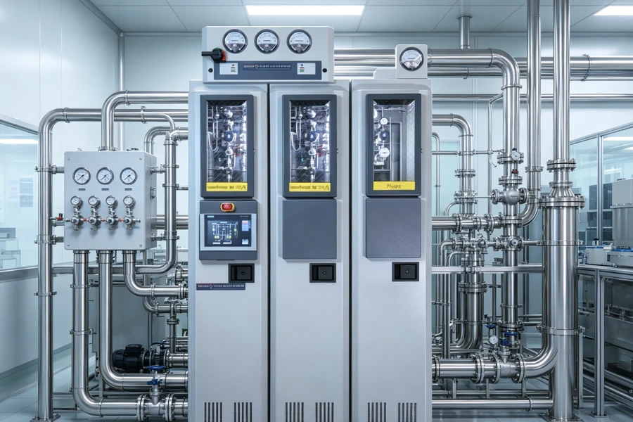
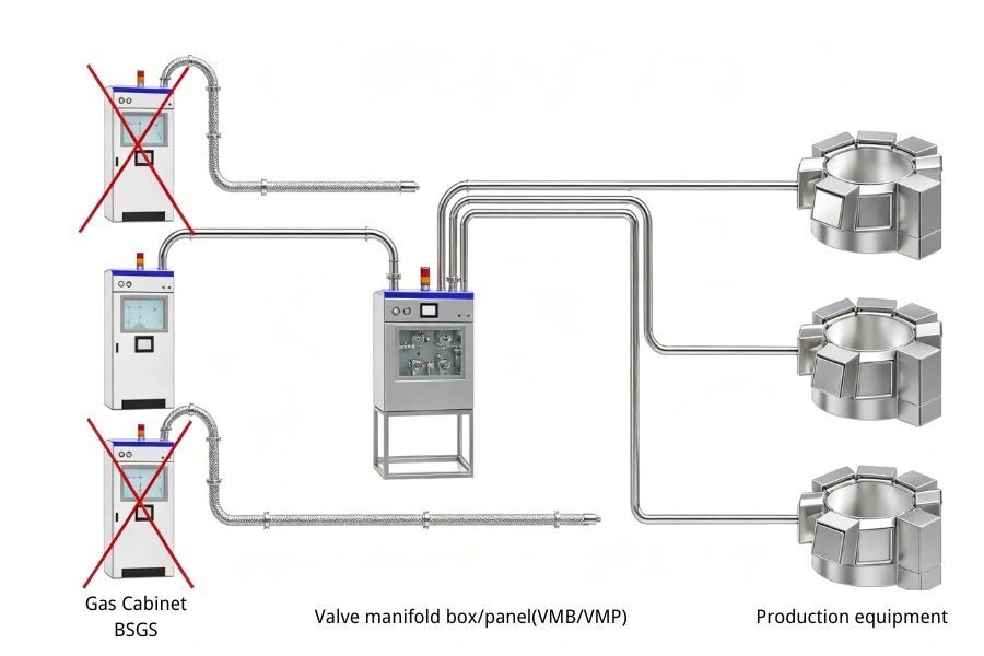
Typical System Layout of Silane Gas Delivery Systems
A gas delivery system for SiH₄ service consists of three primary subsystems that operate as an integrated safety and process unit.
- Gas Cabinet serves as the primary containment and safety barrier for gas cylinders
- Valve Manifold Box (VMB) distributes gas to process tools and provides localized control
- High-purity piping connects system components using welded and face-seal fittings
Control systems based on PLC or DCS architecture manage interlocks, purge sequences, and emergency shutdown functions.
Each subsystem must be designed to operate independently under fault conditions while maintaining overall system integrity.
Key Design Requirements for Silane Gas Cabinets
Purge System Design and Performance Requirements
The purge system must ensure oxygen and moisture levels remain below defined thresholds prior to introduction of the pyrophoric gas stream.
- Inert gas purge using nitrogen or argon must achieve oxygen concentration below 1 ppm before system activation
- Purge cycles must include a minimum of three vacuum and pressurization sequences for cylinder changeover
- Purge gas velocity must be maintained at or above 0.3 meters per second to ensure effective displacement
Acceptance criteria must include verified outlet oxygen concentration below 0.5 percent or process gas concentration below the lower explosive limit.
Leak Detection and Interlock Requirements
Leak detection systems must continuously monitor gas concentration and trigger automated responses within defined thresholds.
- Electrochemical sensors must be installed in gas cabinet enclosures, exhaust ducts, and VMB compartments
- Low-level alarms must be configured between 0.1 ppm and 0.5 ppm
- High-level alarms must trigger interlock actions below 50 percent of STEL
Interlock actions must include immediate closure of cylinder isolation valves, activation of exhaust systems, and initiation of emergency purge.
Redundant sensors with voting logic must be implemented to reduce false shutdown events.
Material Selection and Welding Requirements
All wetted materials must be compatible with SiH₄ service and support ultra-high purity gas delivery.
- Tubing and fittings must use 316L stainless steel with electropolished internal surfaces
- Surface roughness must not exceed Ra 0.25 micrometers
- All connections must use metal gasket face-seal fittings
Welded joints must meet helium leak test criteria of ≤ 1×10⁻⁹ atm·cc/sec. Each weld must be documented with welding parameters and inspection records.
Design Requirements for Valve Manifold Boxes (VMB)
Pressure Reduction and Flow Control Requirements
The manifold system must reduce cylinder pressure to process-level pressure while maintaining stable flow conditions.
- Dual-stage pressure regulators must be used to reduce pressure from up to 2000 psi to controlled downstream levels
- Materials for regulator diaphragms must be corrosion-resistant, such as Hastelloy or Monel
Mass flow controllers must be used for precise delivery, compensating for temperature and pressure variations.
Flow Limitation and Isolation Requirements
Flow limitation must prevent uncontrolled gas release in the event of downstream failure.
- Restrictive flow orifices must be sized to limit maximum discharge below explosive release thresholds
- Excess flow valves must automatically shut off when flow exceeds defined limits
Isolation valves must default to a closed position upon loss of power or pneumatic supply.
Redundancy and Fail-Safe Requirements
The manifold system must maintain operation continuity while isolating faults.
- Dual gas supply lines with automatic switchover must be implemented
- Double block and bleed (DBB) configurations must be used for maintenance isolation
Local faults must isolate only the affected branch without interrupting upstream or parallel process lines.
Safety Interlock and Emergency Shutdown Requirements
Emergency shutdown systems must respond to hazardous conditions within defined time limits.
- ESD response time must not exceed 50 milliseconds as defined by SEMI S2
- Interlock systems must include both hardwired and PLC-based logic
Upon activation, the system must:
- Close all isolation valves
- Open vent paths to exhaust or scrubber systems
- Initiate high-flow nitrogen purge
- Activate facility alarms and notify central control systems
System logic must include delay filtering to prevent false activation while maintaining rapid response capability.
System Verification and Testing Requirements
All systems must undergo verification prior to commissioning and after maintenance.
- Helium leak testing must confirm system integrity at ≤ 1×10⁻⁹ atm·cc/sec
- Functional testing must validate interlock response and purge sequence execution
- Pressure testing must confirm regulator stability and relief system operation
Periodic calibration of gas detectors must be performed every 6 to 12 months using certified calibration gases.
System Selection and Design Considerations
System design must align with operational requirements, facility scale, and safety objectives.
- Fully automated systems are required for high-volume semiconductor production
- Redundant power supply and dual sensor configuration must be implemented for critical systems
- Modular valve assemblies must support maintenance without system shutdown
Incorrect component selection can increase risk exposure.
- Flow limiting devices must be sized with a safety margin of at least 20 percent above process demand
- Non-metallic sealing materials must be avoided in high-temperature or high-purity applications
- Welding personnel must be certified to applicable standards such as ASME Section IX
Engineering Support for Silane Gas System Design
In complex SiH₄ handling environments, system performance depends on integration of fluid control, hazard mitigation, and automation logic. These requirements extend beyond equipment specification and require process-level engineering capabilities.
DODGEN applies these capabilities in high-purity fluid systems and hazardous process environments, supporting system-level optimization rather than component-level design.
Key Design Takeaways
Gas manifold and cabinet design for SiH₄ service must comply with international standards and incorporate strict control of purge systems, leak detection, and material integrity.
Automated systems reduce operational dependency and improve consistency. System design must prioritize fail-safe behavior, redundancy, and verifiable performance.
Engineering-driven approaches support stable semiconductor manufacturing operations under high-risk process conditions.