Why Incorrect Evaporator Selection Leads to Product Loss
In heat-sensitive chemical processing, evaporator selection directly affects product stability, yield, and operational continuity.
In applications involving APIs, PLA intermediates, and botanical extracts, elevated temperature or extended residence time is associated with:
- Degradation of active compounds
- Formation of color bodies and impurities
- Accelerated fouling, resulting in unplanned shutdowns
These effects are routinely observed in industrial operation and result in reduced recovery rates and increased maintenance requirements.
Falling film systems are commonly applied in such scenarios. However, performance depends on alignment between material characteristics and equipment design.
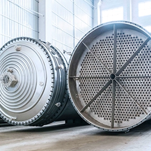
Operating Characteristics of Falling Film Systems in Heat-Sensitive Processing
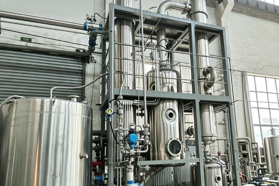
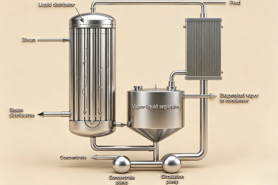
A falling film system distributes liquid at the top of vertical tubes, forming a thin film that flows downward under gravity while heat is applied through the tube wall.
In industrial operation, this configuration is associated with:
- Residence time typically in the range of 5–30 seconds
- Reduced boiling temperature under vacuum, often 40–70 °C
- High heat transfer coefficients due to thin film flow
These characteristics are linked to reduced thermal exposure compared to bulk boiling systems.
Performance stability depends on maintaining uniform film distribution and minimizing fouling across the heat transfer surface.
Material Properties That Determine Evaporator Selection
In industrial practice, evaporator selection is defined by material behavior rather than equipment preference.
Thermal Stability Limit
The maximum allowable temperature before degradation determines the required operating pressure and temperature range.
For systems with degradation thresholds below 60 °C, vacuum operation is typically required to maintain product integrity.
Viscosity Profile
Falling film configurations are generally applied to low and moderate viscosity fluids.
- Typical operating range — below 200 cP
- Extended range with optimized design — up to approximately 1000 cP
Viscosity at both inlet and final concentration must be evaluated, as increasing viscosity reduces film stability and heat transfer.
Fouling and Scaling Tendency
Fouling behavior directly influences heat transfer performance.
Deposits on heat transfer surfaces reduce the overall heat transfer coefficient and require compensating increases in wall temperature to maintain evaporation rate.
Materials with high fouling tendency are often processed using alternative configurations or require enhanced anti-fouling design.
Foaming Characteristics
Foaming behavior varies widely across biochemical and surfactant-containing systems.
Excessive foaming may result in:
- Entrainment losses
- Reduced vapor-liquid separation efficiency
Mitigation is typically achieved through separator design and process control.
Solids Content and Crystallization Behavior
Suspended solids or early-stage crystallization may interfere with liquid distribution and film formation.
In such cases, pre-treatment or alternative evaporation technologies are evaluated to maintain stable operation.
Conditions Where Falling Film Systems Are Not Applicable
Falling film configurations are not universally applicable.
In industrial practice, alternative systems are selected under the following conditions:
- Viscosity exceeds approximately 1000 cP during processing
- Fouling or scaling develops rapidly at low concentration levels
- Crystallization occurs within the evaporator
- Feed streams contain significant suspended solids
Under these conditions, forced circulation or wiped film systems are typically applied.
Design Features That Support Heat-Sensitive Operation
System performance is determined by design execution.
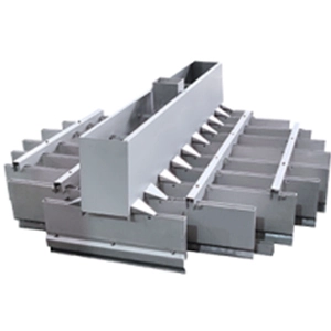
Liquid Distribution System
Uniform liquid distribution is required to maintain continuous film coverage.
Inadequate distribution leads to localized dry zones, resulting in overheating and fouling.
Industrial designs typically maintain stable distribution at 30–40 percent of nominal load.
Heat Transfer Geometry
Typical tube configurations include:
- Length — 4–8 m
- Diameter — 25–65 mm
Increasing tube length increases surface area but also introduces pressure drop considerations. Design optimization balances both factors.
Vacuum System Configuration
Vacuum systems are designed based on total gas load, including non-condensable gases.
Insufficient vacuum capacity results in increased boiling temperature and associated thermal exposure.
Material Selection
Material of construction is defined by corrosion resistance and process requirements.
- Product contact surfaces — typically SUS316L or higher
- Weld surfaces — finished to meet CIP and GMP requirements
Material selection influences both durability and product purity.
Fouling Impact and Control Measures
Fouling is a primary operational constraint.
A medida que avanza el ensuciamiento:
- Heat transfer coefficient decreases
- Required heating temperature increases
- Product degradation risk increases
Design-Based Mitigation
- Maintain minimum wetting rate, typically above 70 percent of design flow
- Apply electropolished internal surfaces
- Optimize recirculation where required
Operational Control
- Implement scheduled CIP procedures
- Monitor pressure drop and thermal performance
- Apply appropriate cleaning protocols
Fouling management is directly linked to long-term system reliability.
Energy Configuration Selection Criteria
Energy design is evaluated in relation to both thermal sensitivity and operating cost.
Single Effect Systems
- Steam economy — approximately 0.8–1.0
- Lower residence time compared to multi-effect systems
Applied in small-scale or highly sensitive processes.
Sistemas multiefectos
- Steam consumption reduced by approximately 30–50 percent per additional effect
- Applied in continuous large-scale operation
However, additional effects increase total residence time and reduce temperature gradients.
MVR Systems
Mechanical vapor recompression reuses vapor energy and reduces external steam demand.
Application depends on energy cost structure and plant scale.
Comparison of Evaporator Configurations
| Configuration | Tiempo de permanencia | Thermal Suitability | Viscosity Range | Limitation |
|---|---|---|---|---|
| Falling film system | 5–30 s | Alta | up to ~1000 cP | Fouling sensitivity |
| Rising film system | 1–3 min | Moderado | low viscosity | Gradiente de temperatura |
| Forced circulation system | 5–15 min | Moderado | up to ~5000 cP | Long residence time |
| Wiped film system | <10 s | Alta | very high viscosity | High capital cost |
Falling film systems are commonly applied where thermal sensitivity and moderate viscosity are present.
Failure Mechanisms in Incorrect Evaporator Selection
Observed failure patterns in industrial operation typically follow a consistent sequence:
- Non-uniform distribution leads to dry zones
- Local overheating initiates fouling
- Heat transfer performance declines
- Heating temperature increases to maintain capacity
- Product degradation occurs
This sequence results in reduced yield and increased maintenance frequency.
Step-by-Step Evaporator Selection Framework
Step 1 — Define Material Limits
Determine:
- Thermal degradation profile
- Viscosity variation across concentration range
Step 2 — Calculate Evaporation Load
Establish required evaporation rate based on feed and target concentration.
Step 3 — Select Energy Configuration
Evaluate operating hours and energy cost to determine single, multi-effect, or MVR configuration.
Step 4 — Confirm Compliance Requirements
Assess:
- Cleaning requirements
- Material standards
- Surface finish
Step 5 — Evaluate Downstream Integration
Evaporation performance must align with downstream processes such as crystallization or drying.
Impact of Evaporation on Downstream Processing
Evaporation defines feed conditions for subsequent processing.
Variations in temperature and concentration affect:
- Crystallization yield
- Pureza del producto
- Process stability
In industrial systems, evaporator selection is typically evaluated within the full process chain rather than as an isolated unit.
Common Operating Issues and Mitigation
- Dry zones — maintain adequate feed rate and clean distribution system
- Foaming — adjust separator design or dosing strategy
- Vapor entrainment — increase separation efficiency
- Vacuum instability — maintain condenser and vacuum equipment
- Capacity decline — monitor fouling and heat transfer
Selection Summary
Selection of a falling film system for heat-sensitive chemical processing is defined by:
- Material properties
- Process requirements
- Energy configuration
- Integration with downstream systems
When these factors are aligned, falling film configurations provide stable low-temperature evaporation with high efficiency.
System performance depends on engineering execution rather than equipment category alone.