3. Structural Units and Industrial Designs of FSD Systems
FSD systems generally consist of two core components:
Heat exchanger or preheater
Flash chamber
Performance is strongly influenced by melt distribution, surface renewal, and heat transfer efficiency.
Below is a structured review of representative industrial approaches.
3.1 Preheater Design and Heat Exchange Optimization
Preheaters are central to FSD efficiency. Their purpose is to:
Rapidly and uniformly heat high-viscosity melt
Minimize local overheating
Promote controlled vapor generation
Common configurations include:
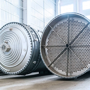
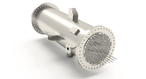
Tubular heat exchangers
Static mixer-equipped tubes
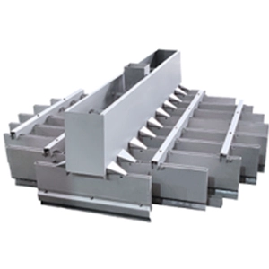
Radial narrow-slot channels
Horizontally stacked disc structures
Honeycomb internal exchangers
Advanced designs introduce:
Temperature gradient control
Optimized groove geometry
Improved melt distribution devices
Uniform heating reduces localized degradation and stabilizes downstream flashing.
3.2 Flash Chamber Configuration and Residence Time Control
Flash chambers operate under vacuum and may use:
Thermal oil jackets
Steam heating
Electric heating during startup
Critical operational parameters include:
Liquid level control
Residence time
Vacuum stability
Excessive residence time increases risk of degradation. However, in rubber-modified systems, moderate thermal exposure can stabilize dispersed rubber morphology and improve impact resistance.
Liquid level is typically controlled via automated pump speed regulation. Auxiliary heating coils may compensate for evaporative cooling but are only suitable for non-crosslinking systems.
3.3 Melt Discharge Pump Selection
Discharge pumps must:
Operate under vacuum
Accommodate high-viscosity melt
Provide large feed openings
Gear pumps and screw pumps are commonly used.
3.4 Condensation and Vacuum System Design
Efficient condensation enhances vacuum stability.
Typical systems include:
Superheated steam coolers
Tubular condensers
Multi-stage steam jet vacuum pumps
Mechanical vacuum pumps are less common in large-scale installations.